1-8 (No.MB366)
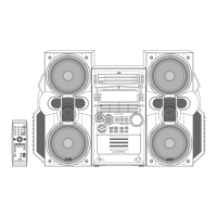
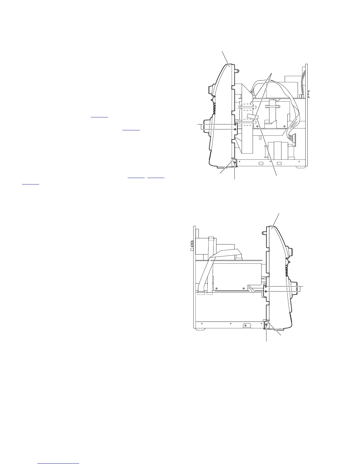
3.1.2 Removing the front panel assembly
(See Figs.4 to 7)
• Remove the metal cover.
(1) From the right side of the main body, remove the spacer fix-
ing the card wire and remove the card wire from the sec-
tions a. (See Fig.4.)
Reference:
When reassembling, pass the card wire through the sec-
tions a as before. (See Fig.4.)
(2) From the both sides of the main body, remove the four
screws B and two screws C attaching the front panel as-
sembly. (See Figs.4 and 5.)
(3) From the top side of the main body, disconnect the card
wire from the connector FW101
on the FL board. (See
Fig.4.)
(4) Disconnect the wire from the connector AW102
on the am-
plifier board. (See Fig.6.)
(5) From the both and bottom sides of the main body, release
the joints (b, c) and remove the front panel assembly from
the main body in the direction of the arrow. (See Figs.4 to
7.)
Reference:
Remove the main board from the connectors (FW302
, FW303,
FW304) on the volume board of the front panel assembly at
the same time. (See Fig.6.)
Fig.4
Fig.5
Front panel assembly
Spacer
b
a
C
B
Front panel assembly
b
C
B
 Loading...