1-6 (No.MB556)
SECTION 3
DISASSEMBLY
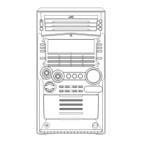
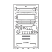
3.1 Main body
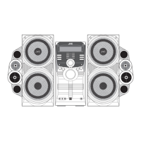
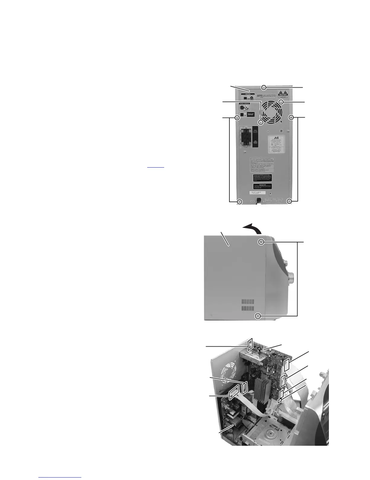
3.1.1 Removing the top cabinet
(See Fig.1, 2)
(1) From the back side of the main body, remove the five
screws A attaching the top cabinet. (See Fig.1)
(2) From the both side of the main body, remove the four
screws B attaching the top cabinet. (See Fig.2.)
(3) Remove the top cabinet from the main body while lifting the
rear section of the top cabinet in the direction of the arrow.
(See Fig.2)
3.1.2 Removing the fan
(See Fig.1, 3)
• Remove the top cabinet.
(1) From the back side of the main body, remove the two
screws C attaching the fan to the rear cabinet. (See Fig.1)
(2) Remove the connector wire from the connector CN108
of
the AMP board. (See Fig.3)
(3) Take out the fan from the main body.
Fig.1
Fig.2
Fig.3
Top cabinet
AA
C
A
C
Top cabinet
B
SMCN01
SMCN02
AMP board
SMPS board
CN102
CN101
CN103
CN104
CN108
 Loading...