EasyManuals Logo
Home>JVC>Car Receiver>KD-G501

JVC KD-G501 Service Manual

JVC KD-G501
57 pages
To Next Page IconTo Next Page
To Previous Page IconTo Previous Page
Page #7 background imageLoading...
Page #7 background image
(No.MA038)1-7
SECTION 3
DISASSEMBLY
3.1 Main body
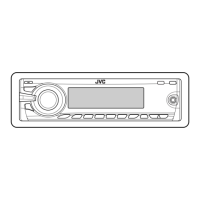
3.1.1 Removing the front panel assembly
(See Fig.1)
(1) Push the detach button in the lower right part of the front
panel assembly and remove the front panel assembly.
Fig.1
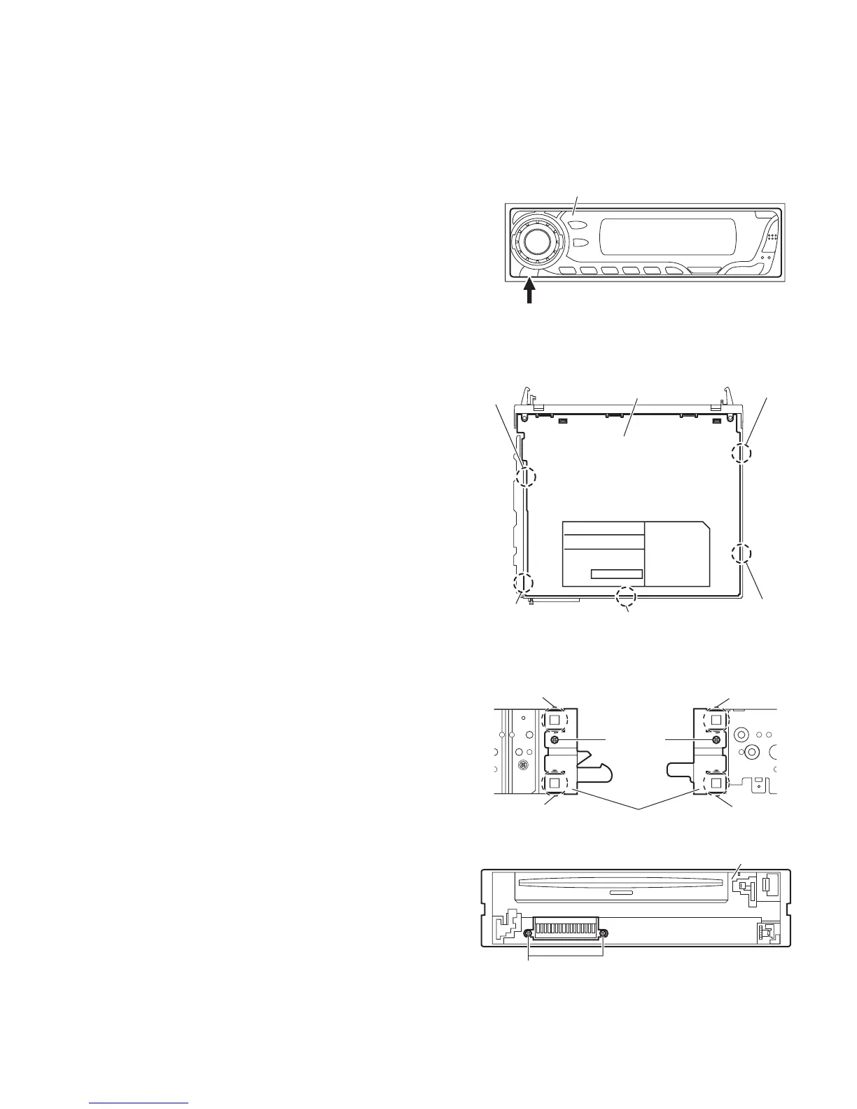
3.1.2 Removing the bottom cover
(See Fig.2)
(1) Turn the main body up side down.
(2) Insert a screwdriver under the joints to release the two
joints a on the left side, two joints b on the right side and
joint c on the back side of the main body, then remove the
bottom cover from the main body.
CAUTION:
When releasing the joints using a screwdriver, do not damage
the main board.
Fig.2
3.1.3 Removing the front chassis assembly
(See Figs.3 and 4)
Prior to performing the following procedures, remove the front
panel assembly and bottom cover.
(1) From the both sides of the main body, remove the two
screws A attaching the front chassis assembly. (See
Fig.3.)
(2) From the front side of the main body, remove the two
screws B attaching the front chassis assembly. (See
Fig.4.)
(3) Release the two joints d and two joints e from the both
sides of the main body, then remove the front chassis
assembly toward the front. (See Fig.3.)
Fig.3
Fig.4
Front panel assembly
Detach button
Bottom cover
Joint b
Joint b
Joint c
Joint a
Joint a
Joint d
Joint d
Front chassis assembly
A
Joint e
Joint e
A
B
Front chassis assembly

Other manuals for JVC KD-G501

Questions and Answers:

Question and Answer IconNeed help?

Do you have a question about the JVC KD-G501 and is the answer not in the manual?

JVC KD-G501 Specifications

Audio Amplifier Specifications IconAudio Amplifier Specifications
maximum power output front50 W per channel
maximum power output rear50 W per channel
continuous power output front19 W per channel into 4 Ω, 40 Hz to 20 000 Hz at no more than 0.8% total harmonic distortion
continuous power output rear19 W per channel into 4 Ω, 40 Hz to 20 000 Hz at no more than 0.8% total harmonic distortion
load impedance4 Ω (4 Ω to 8 Ω allowance)
tone control range bass±10 dB at 100 Hz
tone control range treble±10 dB at 10 kHz
frequency response40 Hz to 20 000 Hz
signal-to-noise ratio70 dB
line-out level/impedance2.0 V/20 kΩ load (full scale)
output impedance1 kΩ
CD Player Specifications IconCD Player Specifications
operating voltageDC 14.4 V (11 V to 16 V allowance)
allowable operating temperature0°C to +40°C
dimensions installation size182 mm × 52 mm × 150 mm
dimensions panel size188 mm × 58 mm × 12 mm
mass1.4 kg (excluding accessories)
frequency response5 Hz to 20 000 Hz
dynamic range96 dB
signal-to-noise ratio98 dB
max. bit rate320 Kbps
Tuner Specifications IconTuner Specifications
frequency range FM87.5 MHz to 108.0 MHz
frequency range AM (MW)522 kHz to 1 620 kHz
frequency range AM (LW)144 kHz to 279 kHz
usable sensitivity FM11.3 dBf (1.0 µV/75 Ω)
50 dB quieting sensitivity FM16.3 dBf (1.8 µV/75 Ω)
alternate channel selectivity (400 kHz) FM65 dB
frequency response FM40 Hz to 15 000 Hz
stereo separation FM30 dB
capture ratio FM1.5 dB
sensitivity MW20 µV
selectivity MW35 dB
sensitivity LW50 µV

Related product manuals