(No.MA347)1-5
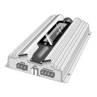
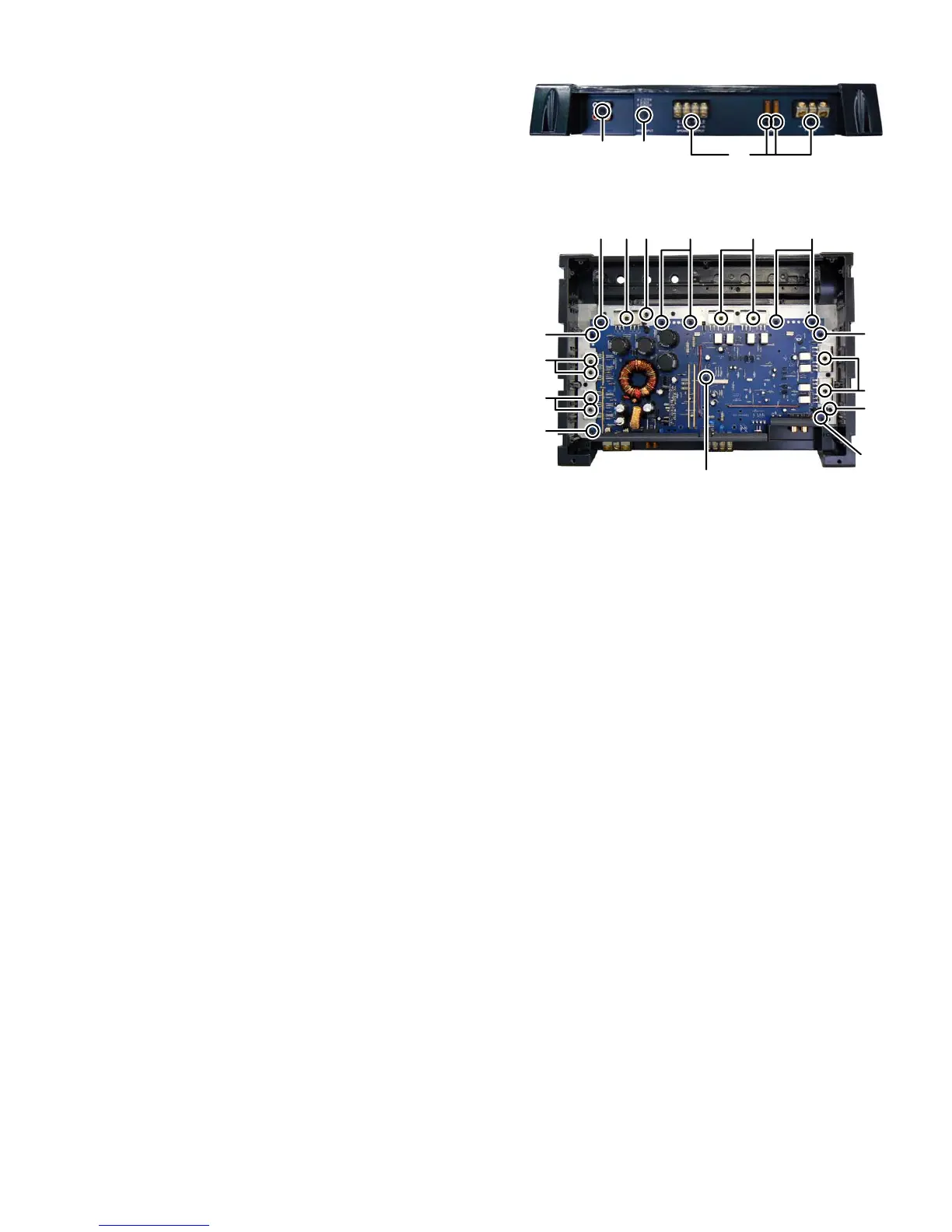
3.1.5 Removing the MAIN BOARD assembly (See Fig.5, 6)
(1) Remove the five screws F and one screw G attaching the
BACK PANEL. (See Fig.5)
(2) Remove the nine screws H attaching the TRANSISTOR
BRACKET. (See Fig.6)
(3) Remove the two screws J attaching the THERMISTOR.
(See Fig.6)
(4) Remove the nine screws K and one screw L attaching the
MAIN BOARD assembly. (See Fig.6)
Fig.5
Fig.6
SECTION 4
ADJUSTMENT
This service manual does not describe ADJUSTMENT.
SECTION 5
TROUBLESHOOTING
This service manual does not describe TROUBLESHOOTING.
F
GF
J
J
K
K
K
K
KKK
L
H
H
HH
H
 Loading...