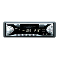
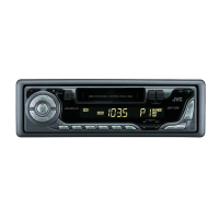
KS-F171
(No.49774)1-7
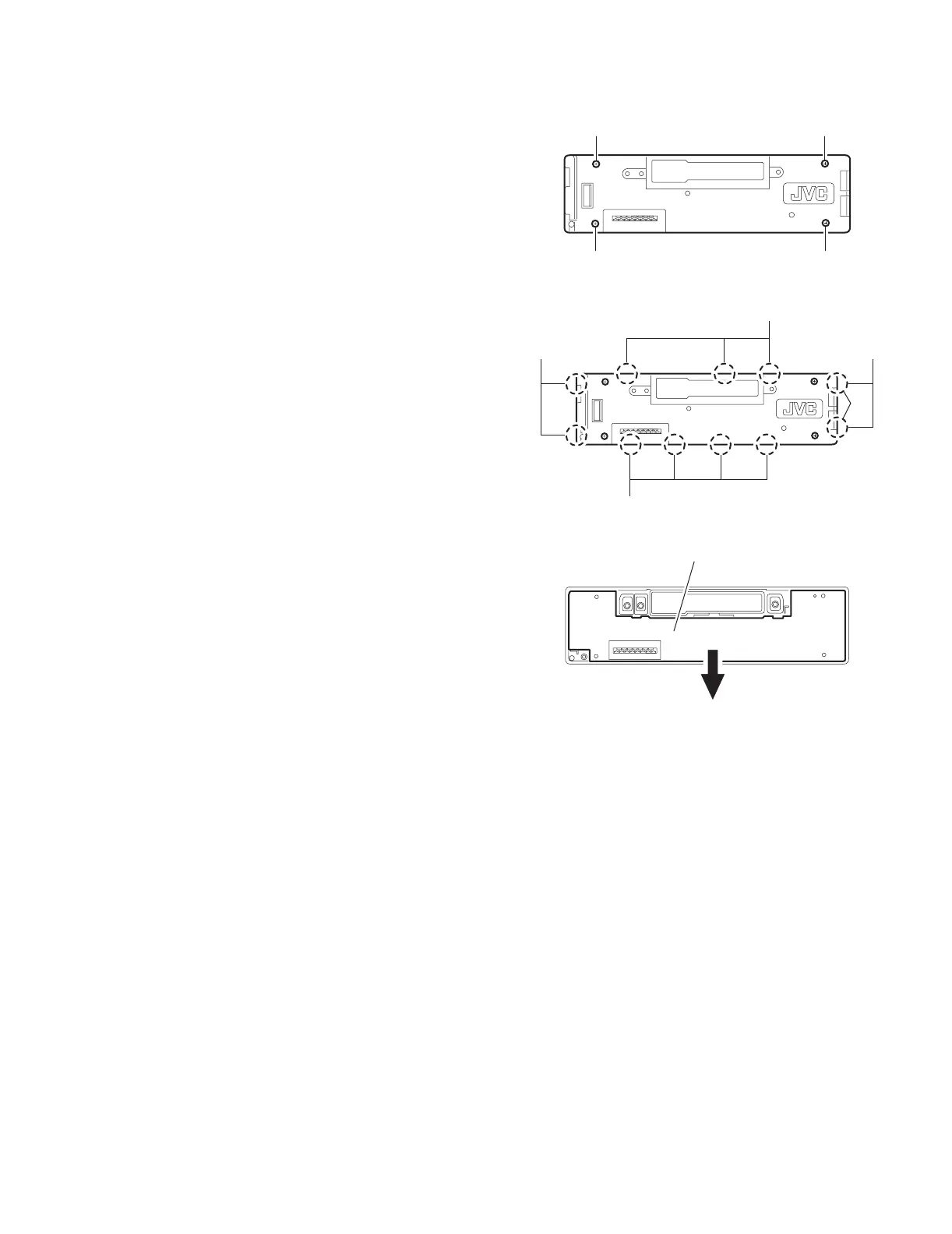
2.1.11 Removing the switch (LCD & key) board
(See Fig.11~13)
• Prior to performing the following procedure, remove the front
panel assembly.
(1) Remove the four screws M attaching the rear cover on the
back of the front panel assembly.
(2) Release the eleven joints h, the front panel and the rear
cover become separate.
(3) Remove the switch board from the rear cover.
Fig.11
Fig.12
Fig.13
M
M M
M
Joint h
Joint h
Joint h
Joint h
Switch (LCD & Key) board
 Loading...