8
100 mm
M4 x 10
M6 x 10
100 mm
100 mm
200 mm
200 mm
*1
M6 x 10
*2
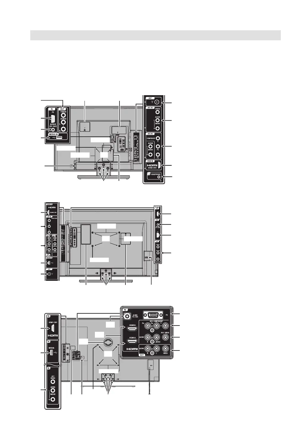
Connections
Note: Before you connect other appliances:
To avoid potentially damaging your set, make sure all items are switched off and disconnected from the mains
power when you make the connections.
Arrange the desired connection.
When you have finished making the connections, reconnect the mains power to the unit and switch it back on.
Connect your antenna as shown below (A). Connections to other equipment is explained further on P.21, 22.
If you have problems with reception, consult a specialist of antenna.
•
•
•
(A) ANT input: Connect to an
analogue cable connection.
(B) AV1/AV2 (LT-24...: AV1) input:
Input for analogue AV-Signal
(Composite) See P.21.
Note: AUDIO input of AV2 is
sharing with COMPONENT
AUDIO input.
(C) COMPONENT input: See P.22.
(D) HDMI/DVI (LT-42.../LT-46...:
HDMI/DVI1/HDMI2/3 / LT32...:
HDMI/DVI1/HDMI2) input: See
P.20.
(E) HEADPHONE jack (LT-24...):
Plug headphones with a mini
plug (3.5 mm) into this jack.
(F) AV Output: Output analogue
AV-Signal (Composite) See P.22.
(G) PC input: See P.19.
(H) AUDIO PC/DVI input: See P.19,
20.
(I) USB input: See P.15.
(J) To hang the television on a wall,
remove these screws and then
remove a stand.
Before performing work spread
cushioning over the base area to
lay the TV on.
(K)
Power supply: Connect the
supplied power cable to an AC
110-240V/50/60Hz mains power
supply only - do not attempt
to connect it to any other type
of supply. Never try to repair a
damaged AC power cord with
isolation-tape - this should
be repaired by a specialist or
replaced. Do not let your pet
loose near the cable. Animals
biting into the cable could receive
a fatal electric shock, and could
cause a hazard to others.
(L) Bracket holes: To attach a wall
mounting bracket (not supplied),
remove the screw (LT-42.../LT-
46...), then attach where indi-
cated in the drawing.
(M) Woofer (LT-42.../LT-46...)
(N)
Service connector cover:
Please do not open this cover.
There is a socket only for service
purpose inside.
(C)
(A)
(B)
(D)
(E)
LT-24...
LT-42.../LT-46...
(G)
(F)
(H)
(I)
(L)
(K)
(J)
(N)
(N)
(N)
LT-32...
(N) (N)
(K)
(D)
(H)
(G)
(F)
(D)
(C)
(B)
(I)
(A)
(L)
(J)
(J) (K)
(L)
(M)
(N)
(A)
(D)
(B)
(I)
(G)
(C)
(B)
(F)
(D)
*1
LT-46...: 400mm
*2
LT-46...: M8x15
(H)
 Loading...