MX-GA3V
1-6
<Disassembly of the main blocks of the set>
Replacement of the fuses and the power IC
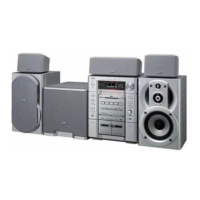
Replacing the fuses (See Fig.1, Fig.3)
Prior to performing the following procedure, remove
the left side BOARD and remove tuner PCB
(Fig.3,BB)
1. Replace the fuses inside.
[Caution]
Be sure to use fuses with the specified ratings.
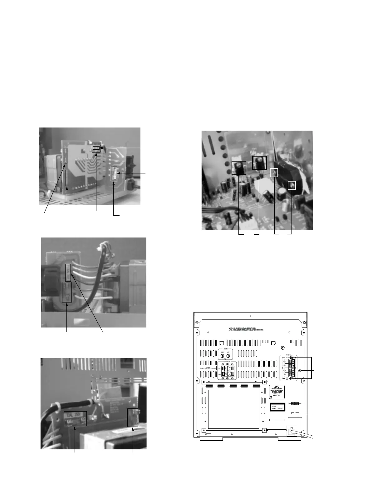
Replacing the heat sink cover (See Fig.3)
1. Remove four screws
B
from the rear panel.
2. Pull the heat sink cover outward.
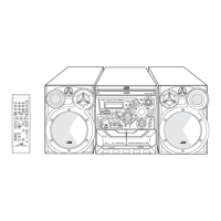
Replacing the power IC (See Fig.2)
Prior to performing the following procedure, remove
the top cover.
1. Remove the two screws
A
from the heat sink
between the power IC.
2. Remove the solder fixing the power IC.
Fig.3
BB
B
VIDEO OUT
110 V
127V
220
V
230V
-240
V
Bottom side Fig.1(A)
CN951
Fuse(F952)
T1.6AL 250V
Fuse(F951)
T2AL 250V
Fuse(F953)
T1.25AL 250V
Add Lable
T2AL 250V
Add Lable
T1.25AL 250V
Component side Fig.1(B1)
Fuse(F953)
T1.25AL 250V
Add Lable
T1.25AL 250V
Component side Fig.1(B2)
Fuse(F951)
T2AL 250V
Fuse(F952)
T1.6AL 250V
WA
Fig.2

 Loading...