EasyManuals Logo

JVC QL-A2 Service Manual

JVC QL-A2
26 pages
To Next Page IconTo Next Page
To Previous Page IconTo Previous Page
Page #17 background image
13.
TXX-124
Schematic
Diagram
NJM4558D-D
SM6415A-4S,
NJM4558D
2S€945
(P,Q)
2SA733
(P,Q)
2SC1775A(F7)
250571
(L,K)
250325
(D,E)
SIBOI-
02
SR103C
X.TAL
182473
[mro36a(QL-az)]
mM-938B(QL-F4)
DOMESTIC
(TXX-124)
Mxx
124A
A
B
[Txx-126-s)
«|
SPEED
SELECT.
SW,
S1
|
33
W3rpm.
C801
10n
/16V
1€801
1¢802
1C803
R603
1K
X803,
X814,
X816,
X817
Oofttg
X01,
X804,
X805,
X806,
X807
Cabs
x813,
X816
X802,
X809,
XB10,
X811,
X812
XB15
Wave
from
1¢801
|
FG
Amp
FH
om
O46}
1
Shaper
Oscillator
/
Fregency
divider
F-V,
P-D
IC
SM6415A-~4S
0810,
0811,
0812,
0813
D804,
0805,
0806,
D807,
0808
£04300-004
0801,
0802,
0803
10ms
|
|
|
|
|
x808
|
aml
2sv
[+
|
|
|
|
|
+
ceoz
F
rowley
=
R810
47K
cB05
=
0.022
C813
10u/16V)
R817
160K
Wy—4-
R818
330K
|
ay
———}
REID
yp.
z
ion
Te?
Re15
3.3K
|
fe
RE47
IK
OI2W)
From
Cartridge
|
=e
R839
390
X805
x8
X809
X810
Y
'©)
X807
X808
O
XBi1
XB12
=
|
TONE-ARM
SHIELD
COVER
of
_J
|
\
Signal
circuit
of
QL-A2
Printed
Circuit
Board
Ass’y
Location
P.C.
Board
Ass’y
Description
TXX-124
Res!
2.7(W)
4.5V
A
Warning
!
yet!
823
220u/S0V
473/50V
EE
&EA(for
Europe
&
Australia)
axx-124€]
oe
AAA
on
AY)
L
0.445
SOPSTRANS,
1.
Be
careful
not
to
allow
metallic
dust,
etc.
to
enter
inside
the
unit,
be
cause
its
motor
is
comprised
of
magnetic
elements.
NJM4558D,
MJM4558D-D
1¢801,
1C803
SM6415A-4S
2SA733
2SC945
2SC1775A
X801,
X803,
X804,
X805
X806,
X807,
X808,
X813
X814,
XB16,
X817,
X818
280571
B
XB02
X809 X810
X81)
xX812
250325
S1B01-
02
0810,
D811,
D812
0813
OLTAGE
SELECTOR
E
Fs
ie
B
Notes:
1.
The
voltage
indicated
in[-_]
is
measured
by
a
tester
having
an
internal
impedance
of
33.k2/V.
©
(_]
33-1/3
rpm
©
(_)
45
rpm
[
]
When
locked
2.
X809
through
X812
should
be
of
the
same
rank.
(There
are
four
different
rankings
avail-
able
on
the
market
as
follows:
2SD571
K1,K2,L1
and
L2
Be
sure
to
use
only
one
rank
of
those
transistors
being
replaced.)
3.
When
replacing
either
of
these
transistors
2SC1775A(F7),
X813
or
X818,
they
should
be
replaced
together
as
a
pair
both
being
of
the
same
rank.
4.
——
indicates
positive
B
power
supply.
5.
=——
indicates
signal
path.
6.
When
replacing
the
parts
in
the
dark-
ened
area
and
those
marked
with
A
,
be
sure
to
use
the
designated
parts
to
ensure
safety.
7.
This
is
the
standard
circuit
diagram.
The
design
and
contents
are
subject
to
change
without
notice.
NJM4558D,
MJM4558D-D
1
3209
yy
pate
42
1CB01,
1C803
hy
1802
254733
2SC945
2SC1775A
2SD571
SM6415A-4S
}
DIAGRAM
Mov
SR103C
192473
D804,
0805,
D806
0807,
D808
D801,
D802,
0803
[-vout.
[|
nov
[r2ov
[CONNECTION]
1-5,
2-6]
3-6,4-1
E
F
2.
After
replacement
of
the
X813
transistor,
apply
KE45RTV
(silicone
adhesive)
or
an
equivalent
material
around
the
transistor
for
thermal
con-
duction.
16
X801,
X803,
X804,
X805
c
B
X802
X809
X810
x811
X806,
X807,
X808,
X813
X812
X814,
X816,
X817,
X818
280325
SIBO1-02
A
X815
0810,
DB11,
DB12
0813
SR103C
182473
K
A
A
K
0804,
D805,
D806
0801,
D802,
D803
0807,
D808
QL-A2
No.
2444

Questions and Answers:

Question and Answer IconNeed help?

Do you have a question about the JVC QL-A2 and is the answer not in the manual?
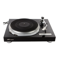
JVC QL-A2 Specifications

General IconGeneral
Drive SystemDirect Drive
MotorDC servo motor
Speeds33 1/3 and 45 rpm
PlatterAluminum die-cast
Wow and Flutter0.03% WRMS
Effective Length220 mm
Overhang15 mm
TonearmStatic balance S-shaped tonearm

Related product manuals