CARTRI DGE REPLACEMENT
~
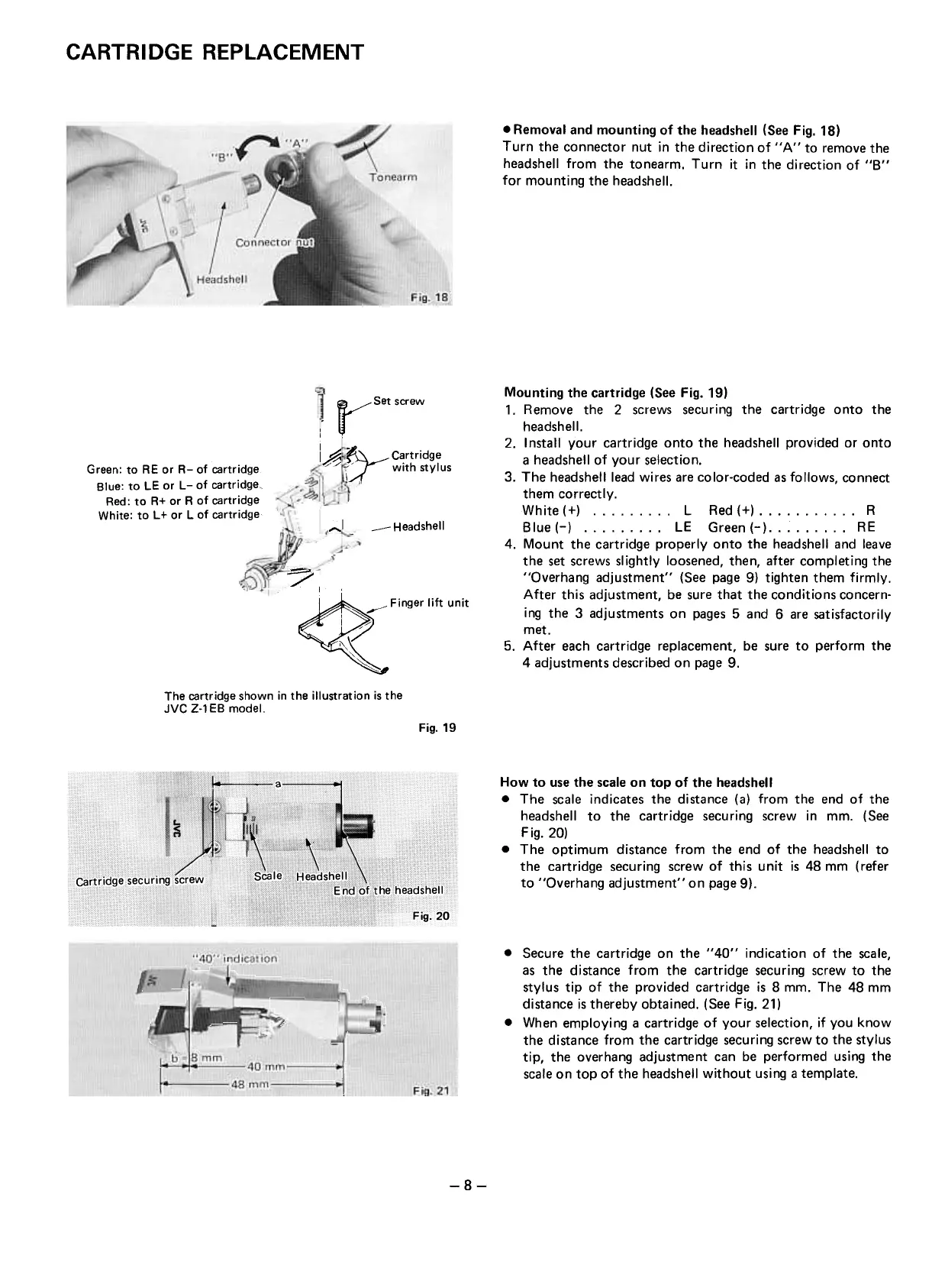
.Removal and mounting of the headshell (See Fig. 18)
Turn the connector nut in the direction of " A " to remove the
headshell from the tonearm. Turn it in the direction of "8"
for mounting the headshell.
.t"set screw
I
lA
~ Cartridge
u with stylus
Green: to RE or R- of cartridge
Blue: to LE or L- of cartridge,
Red: to R+ or R of cartridge
White: to L + or L of cartridge
---Headshell
...".1
?
I'
~ ' Finger lift unit
I /v
~'
~"
~
Mounting the cartridge (See Fig. 19)
1. Remove the 2 screws securing the cartridge onto the
headshell.
2. Install your cartridge onto the headshell provided or onto
a headshell of your selection.
3. The headshelllead wires are color-coded as follows, connect
them correctly.
White(+) L Red(+) R
Blue(-) LE Green(-) RE
4. Mount the cartridge properly onto the headshell and leave
the set screws slightly loosened, then, after completing the
"Overhang adjustment" (See page 9) tighten them firmly.
After this adjustment, be sure that the conditions concern-
ing the 3 adjustments on pages 5 and 6 are satisfactorily
met.
5. After each cartridge replacement, be sure to perform the
4 adjustments described on page 9.
The cartridge shown in the illustration is the
JVC Z-1 EB model.
Fig.19
How to use the scale on top of the headshell
.The scale indicates the distance (a) from the end of the
headshell to the cartridge securing screw in mm. (See
Fig.20)
.The optimum distance from the end of the headshell to
the cartridge securing screw of this unit is 48 mm ( refer
to "Overhang adjustment" on page 9).
.Secure the cartridge on the "40" indication of the scale,
as the distance from the cartridge securing screw to the
stylus tip of the provided cartridge is 8 mm. The 48 mm
distance is thereby obtained. (See Fig. 21)
.When employing a cartridge of your selection, if you know
the distance from the cartridge securing screw to the stylus
tip, the overhang adjustment can be performed using the
scale on top of the headshell without using a template.
-8-
~~
Fig.21
 Loading...