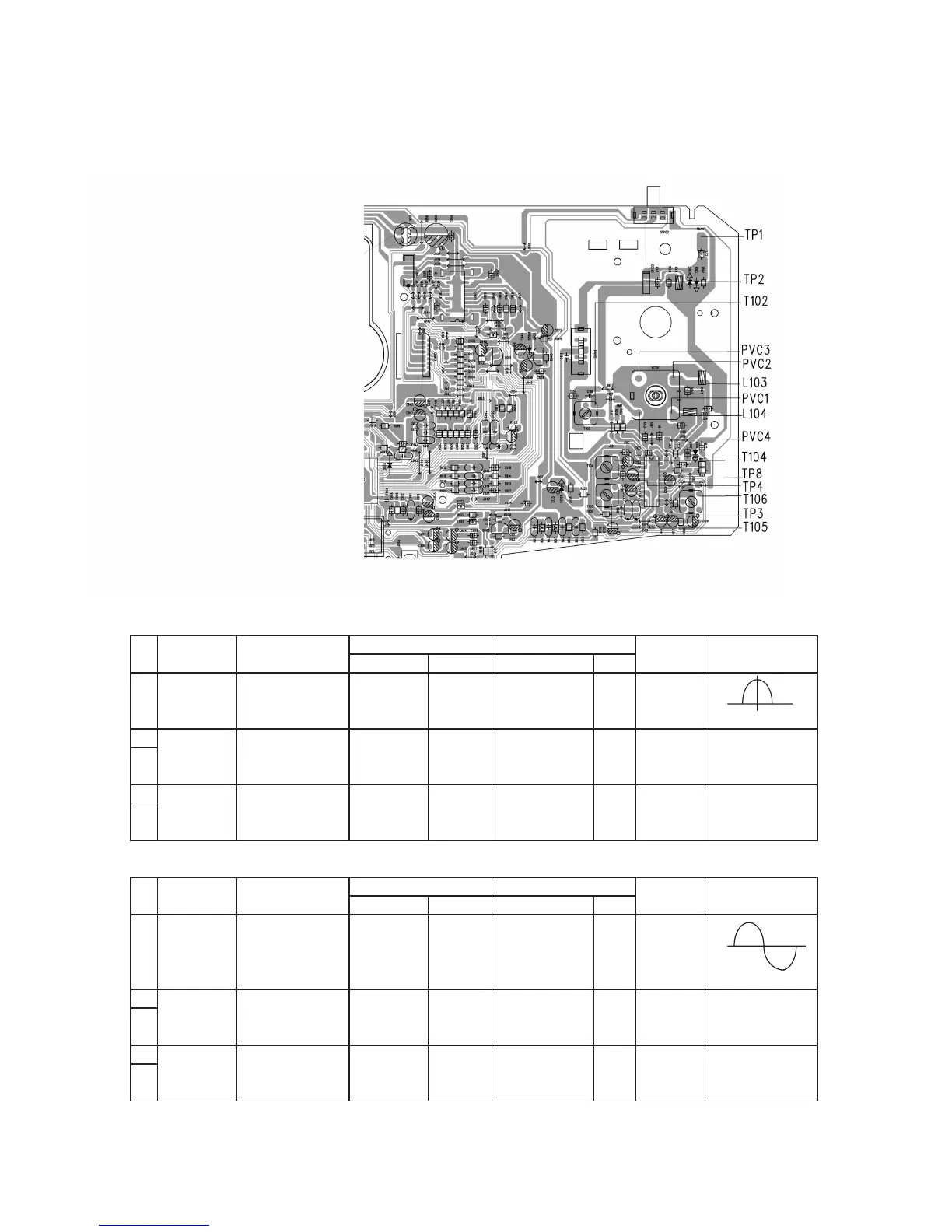
TUNER ADJUSTMENTS
use a plastic screw driver for adjustments.
Adjust the intermediate frequency of AM and FM to the frequency of ceramic filter
.
Supply voltage : DC 12.0 V
Speaker impedance : 8 OHMS
Function switch : RADIO
a. AM Adjustment BAND SELECT SWITCH : AM
ste Adjusting Tuning Input Connection Output Connection Adjustment Oscilloscope
circuit Frequency Measurement input Measurement output parts
1 IF 1000 KHz AM Sweep Loop
TP4(H) T105
(455 / 465KHz) Generior ANT Oscilloscope
TP8(E)
(Non-adjustment)
2 Tuning 520KHz
TP4(H) T102
3 Coverage 1640/1740 KHz -- -- Oscilloscope
TP8(E) PVC4
4 600 KHz AM Signal Loop
TP4(H) MW COIL
5 1400 KHz Generior ANT Oscilloscope
TP8(E) PVC3 Maximum
b. FM Adjustment BAND SELECT SWITCH : FM FM Dummy Antenna : 75 ohm unbalance
ste Adjusting Tuning Input Connection Output Connection Adjustment Oscilloscope
circuit Frequency Measurement input Measurement
output parts
1 IF FM Sweep TP4(H)
TP4(H) T104
(10.7 MHz) 98.0 MHz Generator TP3(E) Oscilloscope
TP8(E) T106
(Non-adjustment)
2 Tuning 87.4 MHz
TP4(H) L104
3 Coverage 108.3 MHz -- FM ANT. Oscilloscope
TP8(E)
PVC2
4 90.0 MHz FM Signal FM ANT
TP4(H)
L103 Confirm with being
5 Tracking 106.0 MHz Generator TP1 (E) Oscilloscope
TP8(E)
PVC1 near by effective
TP2(H) sensitivity
1-12
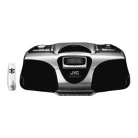
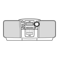
RC-BX33SL
 Loading...