(No.MB723<Rev.003>)1-5
SECTION 2
SPECIFIC SERVICE INSTRUCTIONS
This service manual does not describe SPECIFIC SERVICE INSTRUCTIONS.
SECTION 3
DISASSEMBLY
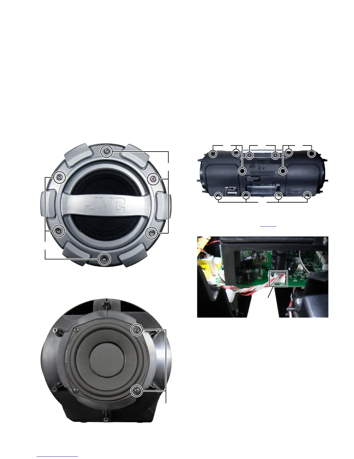
3.1 Main body (Used figure were RV-NB50E)
3.1.1 Removing the Punching panel (See Fig.1)
(1) Remove the twelve screws A attaching the both side of the
Punching panel.
Fig.1
3.1.2 Removing the Rear cabinet (See Fig.2, 3, 4, 5)
(1) Remove the four screws B attaching the both side of the
Subwoofer. (See Fig.2)
Fig.2
(2) Remove the ten screws C attaching the Rear cabinet. (See
Fig.3)
(3) Remove the two screws D attaching the CD mechanism.
(See Fig.3)
Fig.3
(4) Disconnect the connector wire from Power supply board
connected to connector CN101
of the Main board. (See
Fig.4)
Fig.4
A
A
B
C
CCD
CN101
 Loading...