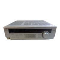
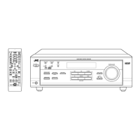
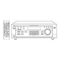
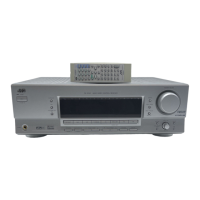
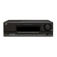
RX-5020VBK/RX5022VSL
1-9
Adjustment method
<Adjustment method>
1.Set the volume control to minimum during this adjustment.(No signal & No load)
2.Set the surround mode OFF.
2.Turn VR301 and VR302 fully counterclockwise to warm up before adjustment.
If the heat sink is already warm from previous use the correct adjustment can not be made.
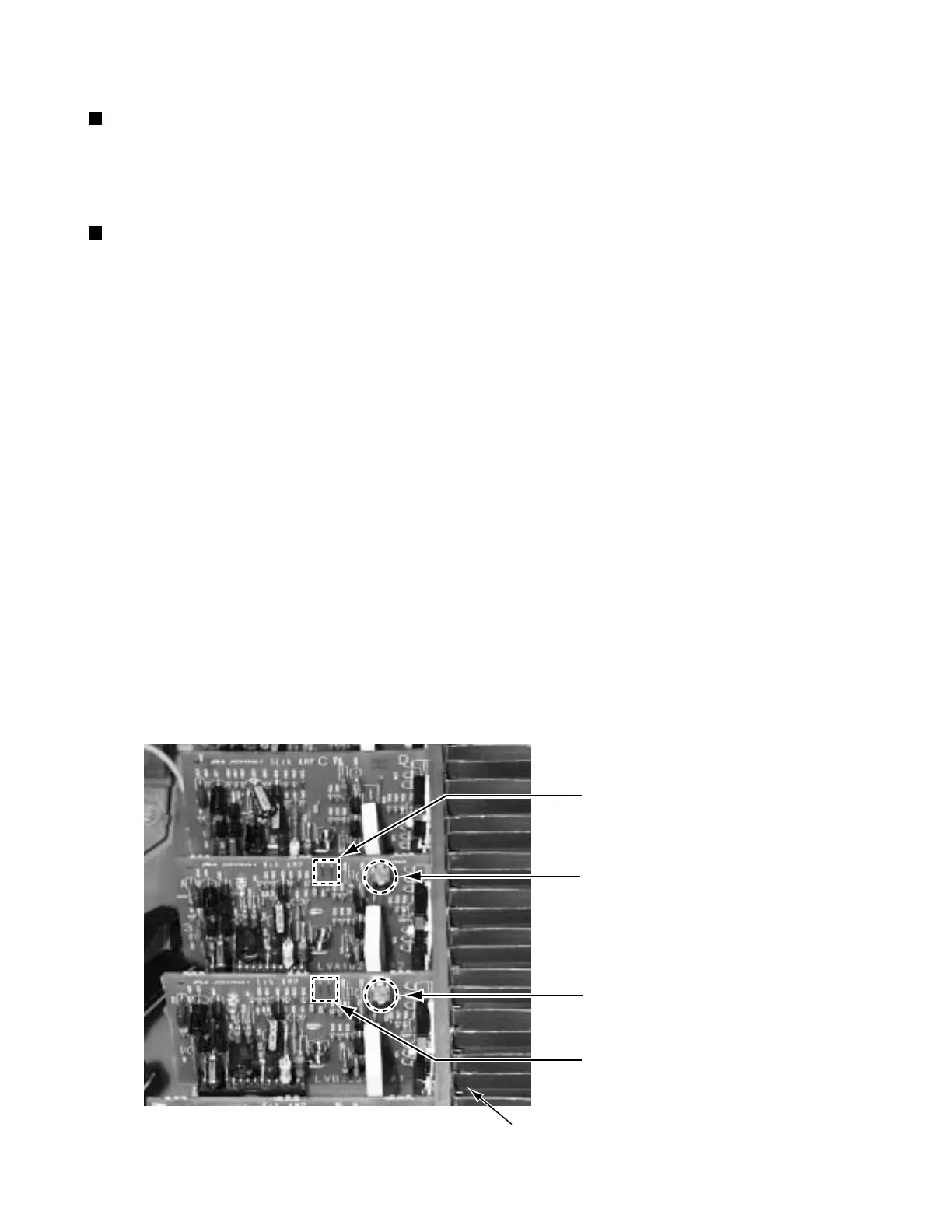
3.For L-ch,connect a DC voltmeter between TP301's B216 and B217 (Lch)
And,connect it between TP302's B218 and B219(Rch).
4.30 minutes later after power on, adjust VR301 for L-ch, or VR302 for R-ch so that the DC voltmeter
value has 1mV~10mV.
1.Tuner range
FM 87.5MHz~108.0MHz
AM(MW) 530kHz~1710kHz
Tuner section
Power amplifier section
TP302(Rch)
VR301 (Lch)
VR302 (Rch)
Heat sink
Adjustment of idling current
Measurement location TP301(Lch) , TP302(Rch)
Adjustment part VR301(Lch) , VR302(Rch)
Attention
This adjustment does not obtain a correct adjustment value immediately after the amplifier is
used (state that an internal temperature has risen).
Please adjust immediately after using the amplifier after turning off the power supply of the
amplifier and falling an internal temperature.
* It is not abnormal though the idling current might not become 0mA even if it is finished to turn variable
resistance (VR301,VR302) in the direction of counterclockwise.
TP301(Lch)
 Loading...