RX-DP10VBK/RX-DP10VSL
RX-DP10RSL
1-12
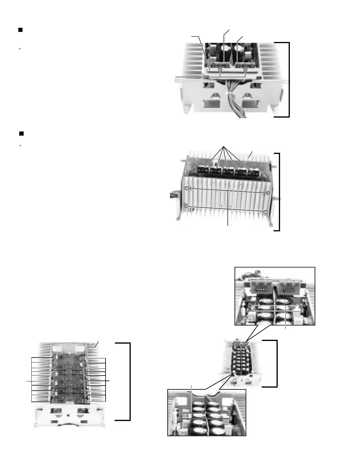
Prior to performing the following procedure, remove
the power amp. assembly, relay board, each pre
amp., amp. sub Lo board and amp. sub Hi board.
Remove the eight screws C attaching the heat sink
both side.
Remove the eight screws D attaching the power ICs
(up side).
Remove the twenty screws D attaching the power
ICs (bottom side).
1.
2.
3.
Removing the heat sink (See Fig.5 to 7)
Prior to performing the following procedure, remove
the power amp. assembly.
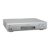
Remove the two screws B attaching the bracket.1.
Removing the amp. sub Lo board & amp.
sub Hi board (See Fig.4)
Fig.6
Fig.7
C
(both side)
D
D
Fig.4
Fig.5
D
B
D
Heat sink
Heat sink
Power ICs
Amp. sub Hi board
Bracket
Power
amp.
assembly
(up side)
Power
amp.
assembly
(bottom side)
Power
amp.
assembly
(bottom side)
Power
amp.
assembly
(up side)
Amp. sub Lo board
 Loading...