RX-DP10VBK/RX-DP10VSL
RX-DP10RSL
1-13
Prior to performing the following procedure, remove
the top cover and the front panel assembly.
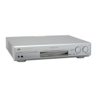
Pull out the volume knob on the front side of the front
panel assembly and remove the nut attaching the FL
display board.
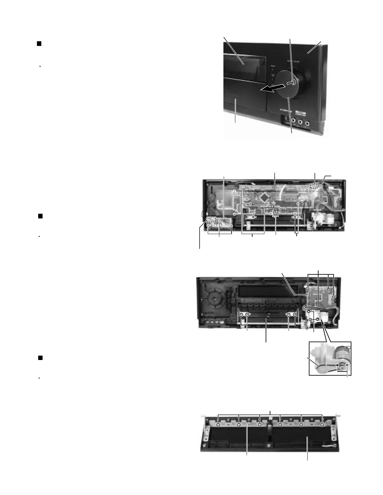
Disconnect the harness from the connector CN973
on the front AV in board.
Remove the three screws A attaching the front AV in
board.
Remove the nine screws B attaching the FL display
board on the back of the front panel.
Disconnect the harnesses from connector CN969,
CN975 and CN982 on the FL display board.
Prior to performing the following procedure, remove
the front panel assembly and the FL display board.
Remove the four screws C attaching the power
switch board.
Remove the three screws D attaching the motor
assembly on the back of the front panel.
Remove the belt and the two screws a attaching the
motor.
1.
2.
3.
4.
5.
Removing the FL display board & front AV
in board (See Fig.1 and 2)
1.
2.
3.
Removing the power switch board &
motor assembly (See Fig.3)
Prior to performing the following procedure, remove
the front panel assembly and the FL display board.
Remove the four screws E attaching the door and
remove the door from front panel assembly.
Remove the six screws F attaching the door input
board.
1.
2.
Removing the door input board
(See Fig.3 and 4)
<Front panel assembly section>
Fig.1
Fig.2
Fig.3
Front panel assembly
Nut
Volume knob
FL display board
Power switch
board
BB
CN982
CN973
Operation switch panel
A
CN969
CN975
Front AV in board
C
D
E
E
Motor assembly
Door input board
F
Door
Door
Belt
Door
Fig.4
a
 Loading...