1-6 (No.MB251)
SECTION 3
DISASSEMBLY
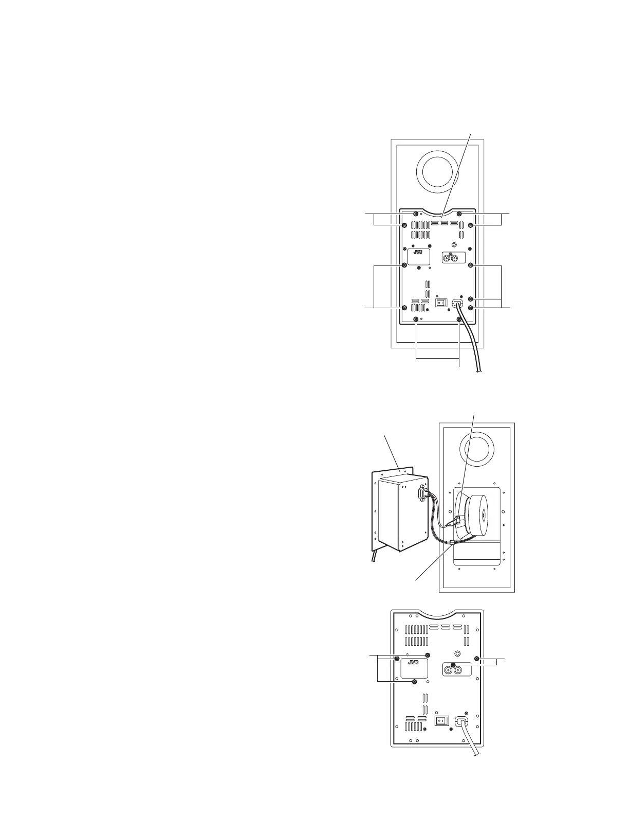
3.1 Removing the Amplifier assembly
(See Figs.1 and 2)
(1) From the back side of the main body, remove the eleven
screws A attaching the amplifier assembly. (See Fig.1.)
(2) Take out the amplifier assembly from the main body.
(3) Disconnect the wire connector from the back side of the
amplifier assembly. (See Fig. 2.)
(4) Disconnect the speaker wire from the speaker terminal.
(See Fig.2.)
3.2 Removing the back panel
(See Figs.1 to 3)
(1) From the back side of the main body, remove the eleven
screws A attaching the amplifier assembly. (See Fig.1.)
Reference:
Remove the amplifier assembly from the main body as
required. (See Fig.2.)
(2) Remove the five screws B attaching the back panel. (See
Fig.3.)
Fig.1
Fig.2
Fig.3
A
A
A
Amplifier assembly
A
A
mplifier assembly
Speaker terminal
Wire connector
B
B
www.freeservicemanuals.info
Published in Heiloo, Holland.
 Loading...