r
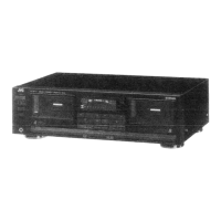
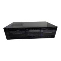
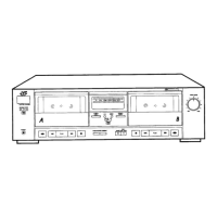
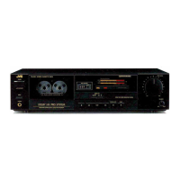
TD-X
g21
M,llcatctrtu
tr
Main Adiustments
1. Equipment and measuring
instÍumonB used for adjuíments
1) Electronic voltmeteÍ
6) Resistor 600 Q
(for
íttenuator
matching)
2)Audio
frequency oscillator
TlDistonion
meter
(bendpar§
filter)
(range:
50-20
kHz
and
outpui
O
dB dith impedance oÍ 600
Ol 8)Wow
flutter meter
3)Attenuator
(impedance:
600
Q)
9)
FÍequency
counteÍ
4)Standard tape.Íor R EC/PB
Maxell UDI
(T99)
-
Normal{SF)
tape
r
Pow.Í rurcG
TDKSA
-
Chmma
(SA)
tap8
-
or equivalent
Set
the line.voltage selector
switó to
240
V/230 V/
JVCME
,
-Metal
tape
:
22OVl127Vl12OVl110V
according to
your
local
5)
Reference tape for
playback
(JVC
TestTape)
voltage.
VTT7l2
(for
tape
speed,
r.yow Íluttèr adi.)
AC 2/O V, 50/60
Hz
(TD-X321A/B)
VTT724
(for
playback
levell ,
AC 220 V, 50/60 Hz
(TD-X321
E/c)
VTT739
(for
playback
Írequency response)
AC t2O
V,60 Hz
(TD-X32IC/J)
vrr703L
(
10
kHz)
(for
head azimuth 8di.)
Ac 2§v
1127
v
t110
v, 50/60
Hz
(Ttlx321U)
2.
Mechanism
adjustment
procedure
o
Notice:
O
dBs
=
O.775
(V)
Item
Adiustment
Adiusting
point
Standard
value
Remarks
Adlusting
motor speed
1.
Connect a
frequency
counter to
the
LINE OUT
terminals.
2.
Play
back the
VTT712 test
tape.
3.
Adjust volume in
motor for
norma!
speed at
3fi)0 Hz.
V RsO1
Normal
speed:
3000
t
15
Hz
Checking
wow and
f lutter
Connect a wow and flutter meterto
LINE
OUT
terminals.
Play back the
VTT712
test tape.
Chèck
to
see if
the reading
of
the
meter
is within
O.16yo
(WRMS).
0.16%
(JIS
WRMS}
lf the reading
becomes
moving
value even
if confirming
to
the
standard,
a
reclaim
may be raised.
Repairs
are
necessary.
Checking
playback
torque
Employ
a torque
testing
cassette tape
for
the
checking, or remove
the
casette cover
and use a torque
gauge.
25-7O
gr-cm
lf
the
standard
torque is
not ob-
tained,
replace
the take-up
disk
assembly.
Checking
fast forward
torque
Measure
the torque
in the
fast
forward
mode in
the
same manner as in the above.
90-150
gr-cm
lf the
standard
torque is
not ob-
tained,
perform
the
following.
1.
Clean
the capstan
belt, the
idler
circumference,
the motor
pulley,
the take-up reel
disk
circumference,
the
flywheel
circumference,
etc.
2.
Replace
the belt
and
idler.
Checking
rewind
torque
Measure the torque
in
the
rewind mode
in the
same
manner as
in
the
above.
90-150
gr-cm lf the
standard
torque is not ob-
tained, clean
the
capstan
belt,
idler, motor
pulley,
flywheel cir-
cumference,
rewinding idter
cir-
cumference,
left reel
disk
circum-
ference, etc.
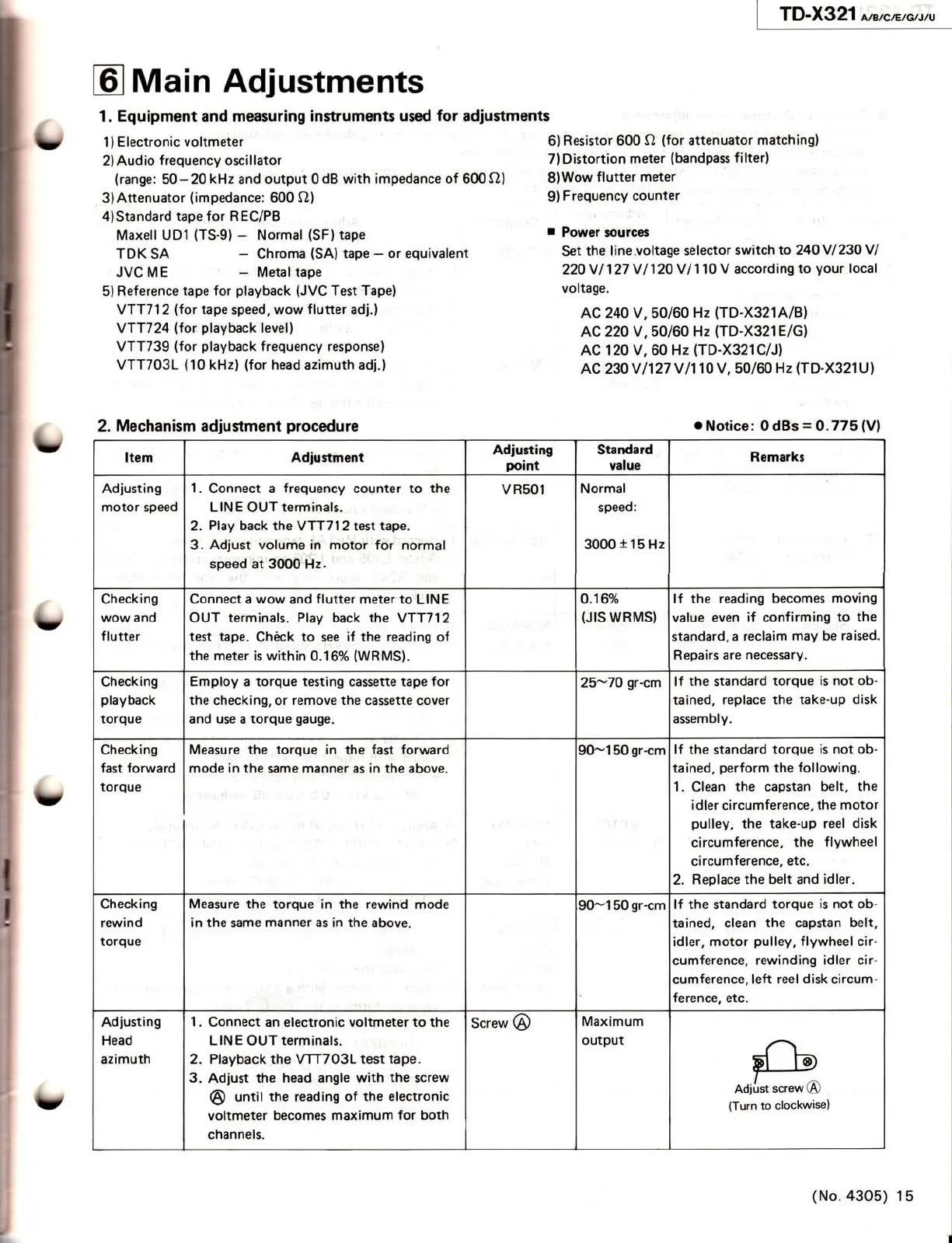
Adiusting
Head
azimuth
1.
Connect
an
electronic voltmeter to the
LINE
OUT
terminals.
2. Playback the
VTTTO3L
test tape.
3.
Adiust
the head angle
with
the
screw
@
until
the
reading
of
the
electronic
voltmeter becomes maximum
for both
channels.
Screw
@
Maximum
output
(No.43O5)
15
 Loading...