1-10 (No.MB427)
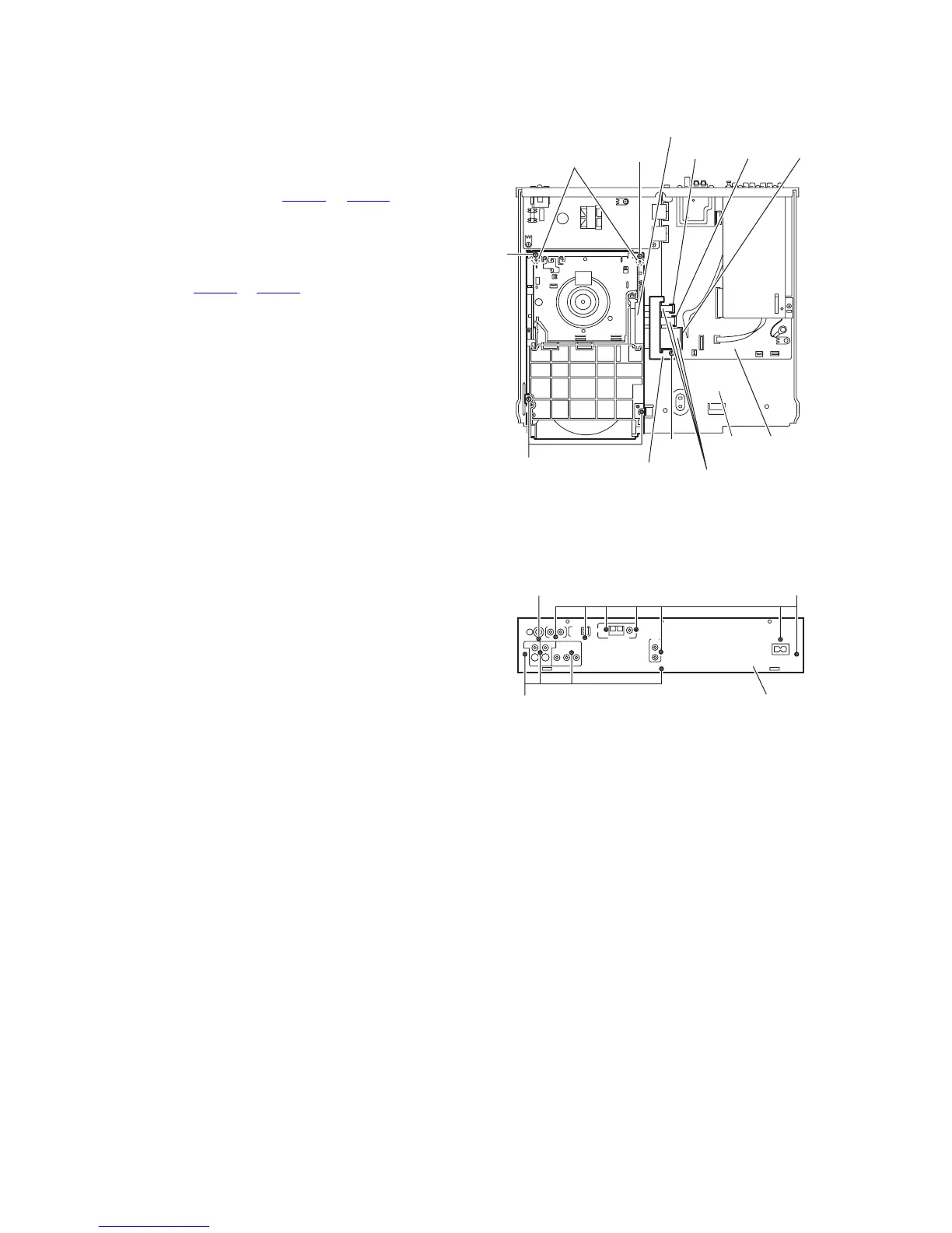
3.1.3 Removing the DVD changer mechanism assembly
(See Fig. 7)
• Prior to performing the following procedures, remove metal
cover and front panel assembly.
(1) From the top side of the main body, remove the screw E at-
taching the wire protection board to the main board.
(2) Take out the wire protection board, and disconnect the
card wires from the connectors (CN401
to CN403) on the
main board.
Reference:
When attaching the wire protection board, attach the
wire protection board after connecting the card wires to
the connectors (CN401
to CN403) on the main board.
(3) Remove the four screws F attaching the DVD changer
mechanism assembly on the bottom chassis.
(4) Take out the DVD changer mechanism assembly in the up-
ward direction.
Reference:
When attaching the DVD changer mechanism assembly, align
the holes of the DVD changer mechanism assembly to the pro-
jections d on the bottom chassis.
Fig.7
3.1.4 Removing the rear panel
(See Fig. 8)
• Prior to performing the following procedures, remove the metal
cover.
(1) From the back side of the main body, remove the screw G
and eleven screws H attaching the rear panel.
Fig.8
Main
board
CN402
Bottom
chassis
DVD changer mechanism assembly
Card wires
Wire protection board
F
F
F
Projections d
CN401
CN403
E
G
H
Rear panel
H
 Loading...