7
English
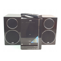
To connect AM and FM antennas
1
Connect the supplied AM loop antenna to the
AM LOOP terminal.
Place the antenna away from the unit and adjust its
position for the best reception.
2
Adjust the position for the FM antenna for
the best reception.
For better reception of both FM and AM
• Make sure the antenna conductors do not touch any other
terminals or connecting cords.
•Keep the antennas away from metallic parts of the unit,
connecting cords, and the AC power cord.
AM loop antenna
(supplied)
IMPORTANT:
Be sure to check that all connections have been made
before plugging in the power cord.
FM antenna
NOW you are ready to plug in the unit.
• If the wall outlet does not match the AC plug, use the
supplied AC plug adaptor.
2
1
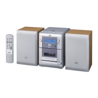
Adjusting the Voltage Selector
Before plugging in the unit, set the correct voltage for your
area with the voltage selector on the bottom of the unit.
Use a screwdriver to move the voltage selector so the voltage
number is the same as the voltage where you are plugging in
the unit. (See the back cover page.)
• DO NOT plug in before setting the voltage
selector on the bottom of the unit and all
connection procedures are complete.
• DO NOT drag the unit when moving it. Dragging
may possibly change the voltage selector setting
accidentally.
VOLTAGE
SELECTOR
AC 220 - 240V
AC 110 - 127V
UX-G1[UW]_04connect_1.p65 05.4.11, 4:37 PM7
 Loading...