(No.MB674<Rev.003>)1-13
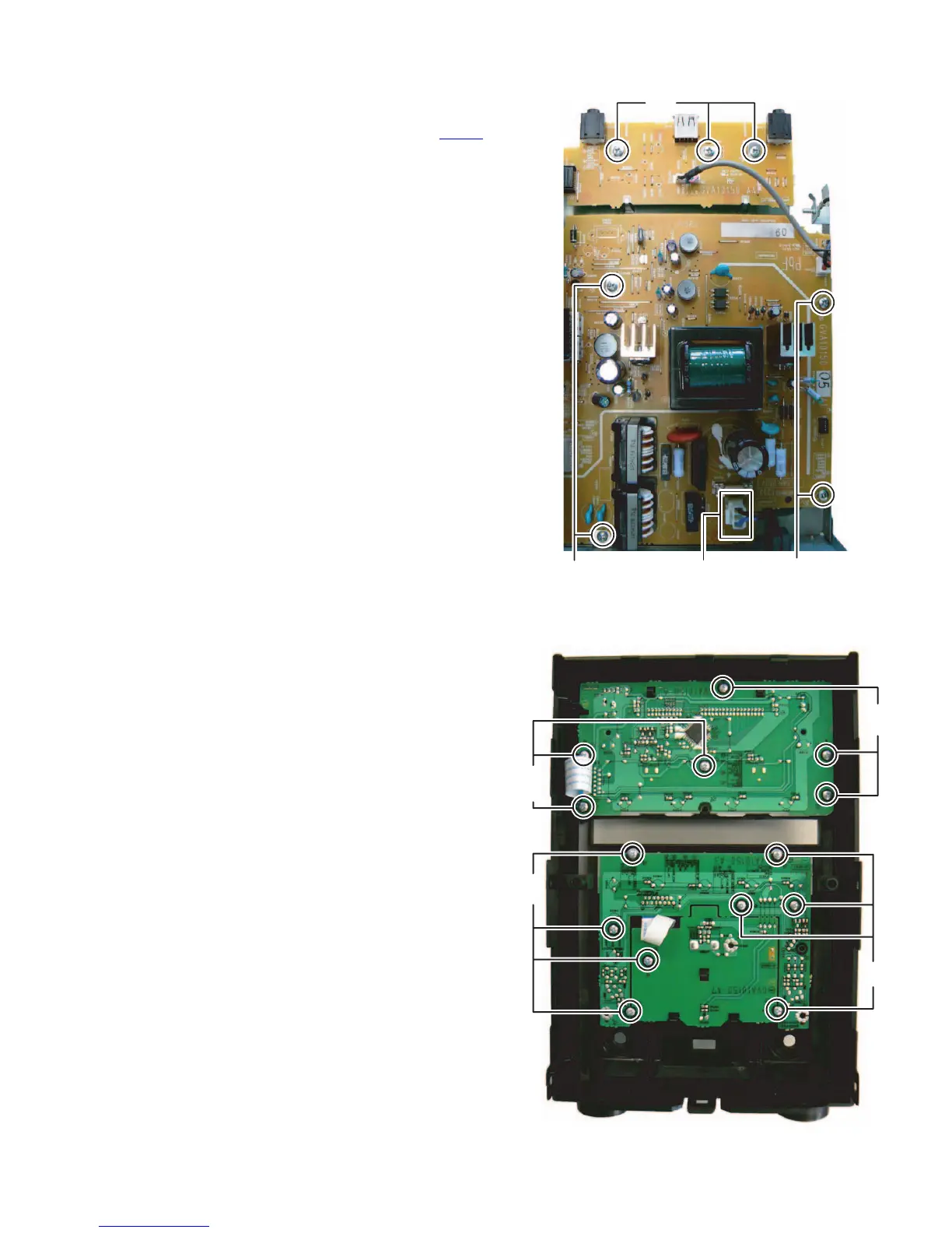
3.1.9 Removing the USB jack board (See Fig.16)
(1) Remove the three screws L attaching the USB jack board.
3.1.10 Removing the Power board (See Fig.16)
(1) Disconnect the power cord connected to connector CN200
of the Power board.
(2) Remove the four screws M attaching the Power board.
Fig.16
3.1.11 Removing the FL board (See Fig.17)
(1) Remove the six screws N attaching the FL board.
3.1.12 Removing the Volume board (See Fig.17)
(1) Remove the volume knob.
(2) Remove the eight screws P attaching the Volume board.
Fig.17
L
MM
CN200
N
N
P
P
 Loading...