(No.MB429)1-5
SECTION 3
DISASSEMBLY
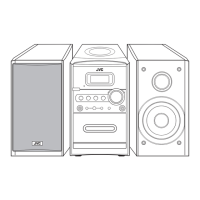
3.1 Main body
3.1.1 Removing the front panel assembly
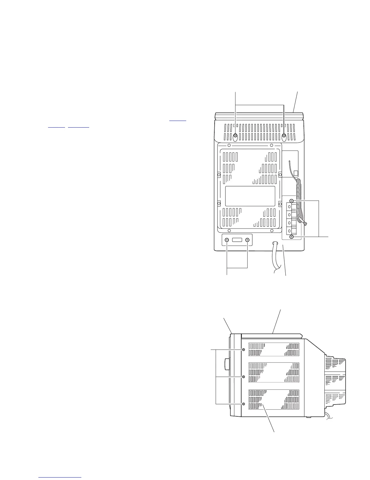
(See Fig.1 to 6)
(1) From the back of the body, remove the two screws A, the
two screws B and the two screws D attaching the front pan-
el assembly.
(2) Remove the six screws E on both sides of the body.
(3) Remove the screw F on the bottom of the body.
(4) Move the front panel assembly in the direction of the arrow
and remove. Disconnect the wire from connector CN102
,
CN402, CON801 on the main board.
Caution:
When reassembling the front panel assembly, fit the right and
left joints a to the notch.
Fig.1
Fig.2
CD mechanism assembly
Rear cover assembly
B
A
D
Front panelh assembly
CD mechanism assembly
Rear cover assembly
E
 Loading...