UX-M5R
1-6
Fig.3
Fig.1
Fig.2
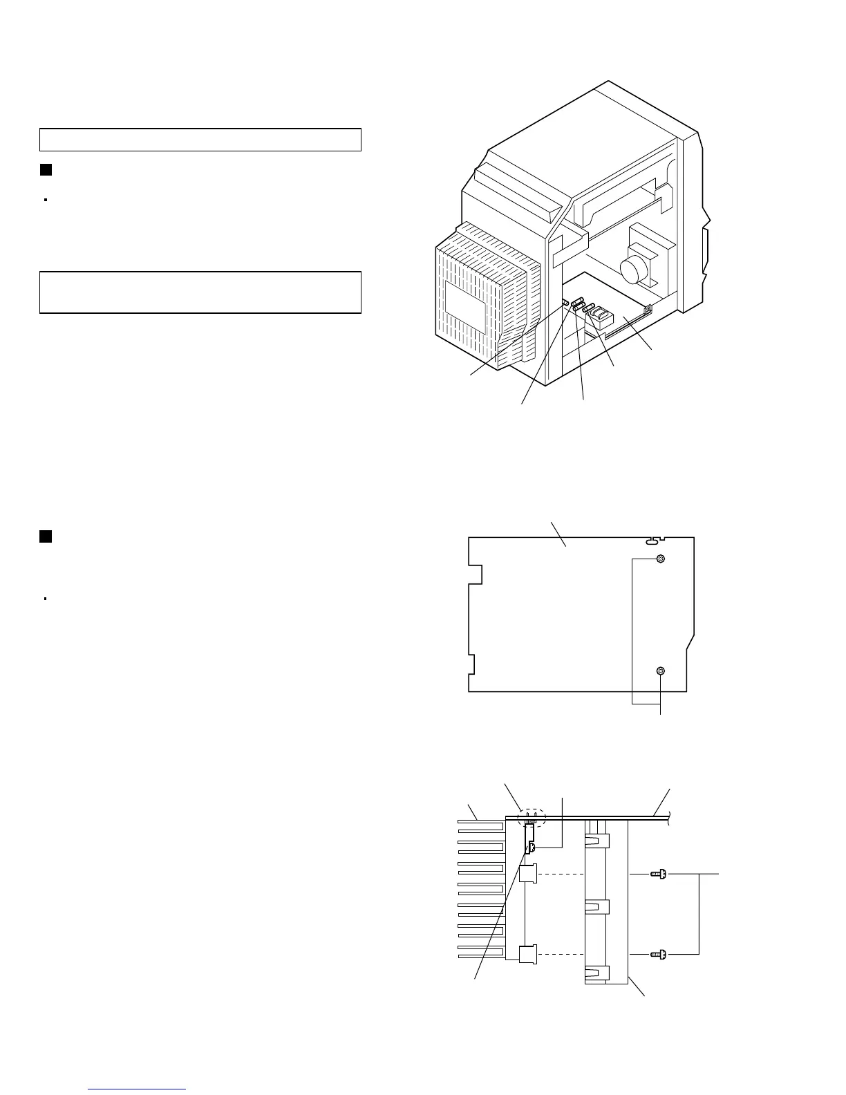
Fuse(F904)
1.6A 250V
Fuse(F901)
1.6A 250V
Power board
Fuse(F903)
2.5A 250V
A
Main board (Reverse side)
B
C
Soldered part a
Heat sink
Bracket
Power amplifier IC
(IC402)
Main board
Fuse(F902)
2.5A 250V
Replacing the fuses (See Fig. 1.)
<Main body section>
Remove the left side panel according to its
disassembly method (see Figs. 6 and 7).
Fuses are located inside the left side panel.
Disassembly method
Replacement of the fuses and power amplifier IC
[Caution] Be sure to replace the required fuses
with designated ones.
Replacing the power amplifier IC on
the main board (See Fig. 2.)
1.
2.
3.
4.
Remove the main board according to its
disassembly method (see Figs. 18 and 19).
From the reverse side of the main board, remove
the two screws A retaining the bracket.
From the forward side of the main board, remove
the four screws B retaining the bracket.
Remove the screw C attaching the power amplifier
IC onto the heat sink.
In order to replace the power amplifier IC, remove
the solder from soldered part a on the reverse side
of the main board.
 Loading...