UX-M5R
1-9
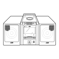
Fig.13
L
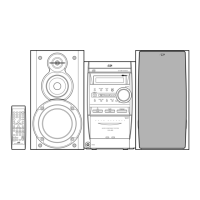
Fig.14
CD & MCU board CD mechanism assembly
CD & MCU board
CD & MCU board
CN603
CN701
Tie bands
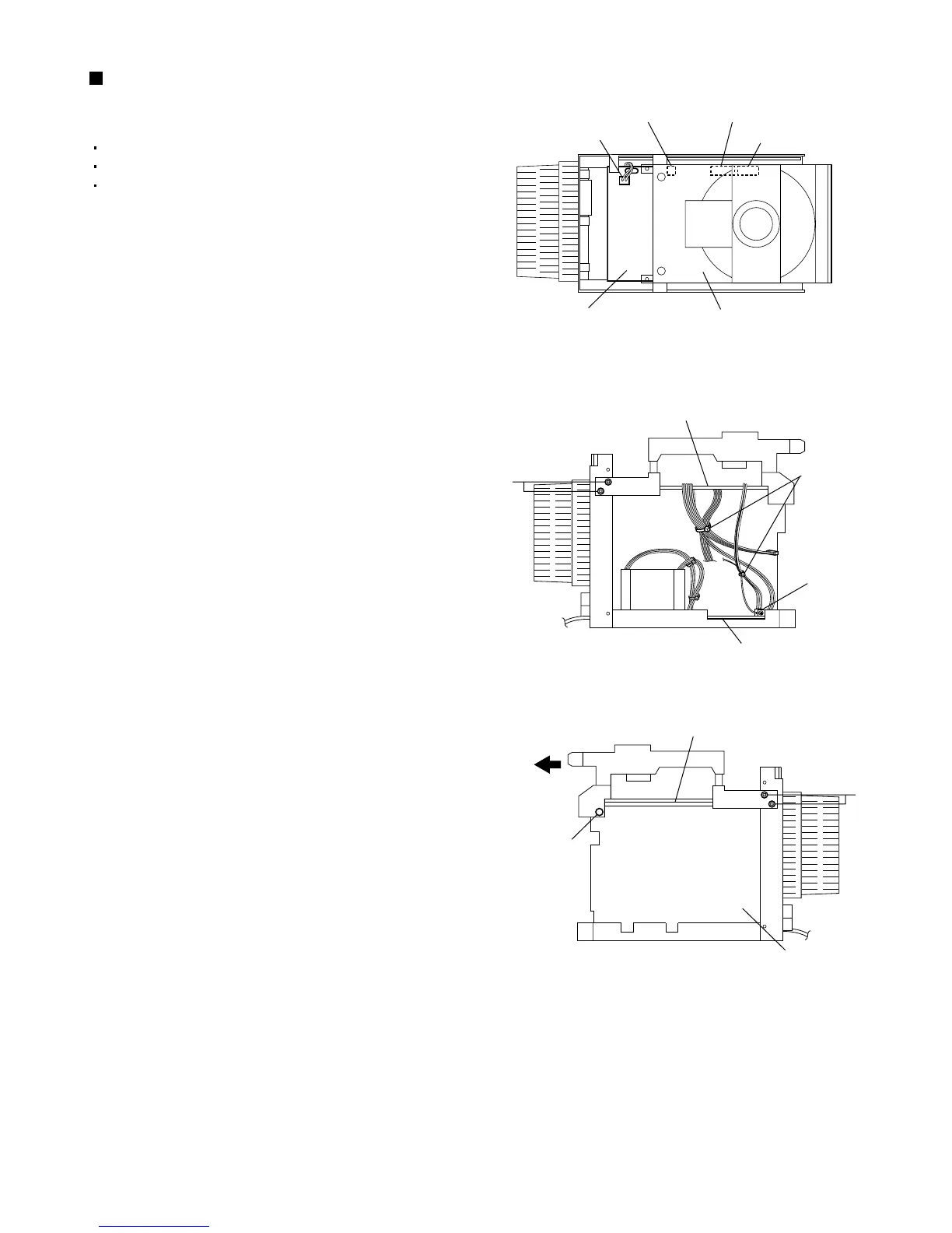
L
Fig.15
Main board
CN601
CN602
Stud
CN902
Power board
Removing the CD mechanism
assembly (See Figs. 13 to 15.)
1.
2.
3.
4.
5.
Remove the left and right side panels.
Remove the top cover.
Remove the front panel assembly.
Disconnect the wires from the four connectors
CN601, CN602, CN603 and CN701 on the CD &
MCU board.
From the left side of the main body, remove the tie
bands bundling the wires.
Disconnect the wire from the connector CN902 on
the power board.
From the left and right sides of the main body,
remove the four screws L retaining the bracket.
Slide the CD mechanism assembly toward the front
and remove it from the stud of the main board.
 Loading...