19
ANTRIEBSTECHNIK
M
3~
PE
L1, L2, L3
3. EMC
Fundamentals
3.1 General
Frequency inverters / servo drives represent electrical equipment designed for use in
industrial and commercial units. In accordance with the EMC directive 89/336/EEC, it
is not obligatory to mark these devices as they represent components to be further
processed by the respective machine and unit manufacturer and are not operable
independently according to the EMC directive. The person installing / operating the
machine / unit is obliged to proove the protective measures demanded by the EMC
directive are complied with. The prescribed ratings can usually be complied with when
using the radio interference voltage filters specified by KEB, and when observing the
following measures and installation guidelines.
The KEB frequency inverter / servo drive is designed to be used in the second
environment as defined in EN 61800-3 (unit with its own supply transformer).
Take additional measures when using it in the first environment (residential and
commercial area connected to public low-voltage mains)!
; Install the cabinet or system correctly.
; To avoid coupled-in noise, separate
• mains / supply lines
• motor lines from inverters / servo actuator
• control and data lines (low-voltage level < 48V)
and leave a space of at least 15 cm between them when installing.
; In order to maintain low-resistance high frequency connections, earthing and
shielding, as well as other metallic connections (e.g. mounting plate, installed units)
must be in metal-to-metal contact with the mounting plate, over as large an area
as possible. Use earthing and equipotential lines with a section as large as possible
(min. 10mm
2
) or use thick earthing strips.
; Only use shielded cable with copper or tin-plated braid, since steel braid is not
suitable for high frequency ranges. The screen must always be installed on the
compensating rail and fastened with clips or guided through the wall of the housing
with metal screw connections. Do not elongate the screen end (pigtails) with
individual conductors!
; If external interference suppression filters are used, then these must be installed
as close as possible to (<30cm from) the interference source and in metal-to-metal
contact with the mouting plate, over as large an area as possible.
; Always equip inductive control elements (contactors, relays etc.) with suppressors
such as varistors, RC-elements or damping diodes.
; All connections must be kept as short as possible and as close as possible to the
earth, as free floating lines work as active and passive aerials.
; Keep connection cables straight (do not bundle). Install a non-assigned wire on
both sides of the protective conductor.
; The flow and return circuit must be twisted when the lines are not shielded, in order
to dampen common-mode noise.
; Further informations are found in the instruction manual part 2/3.
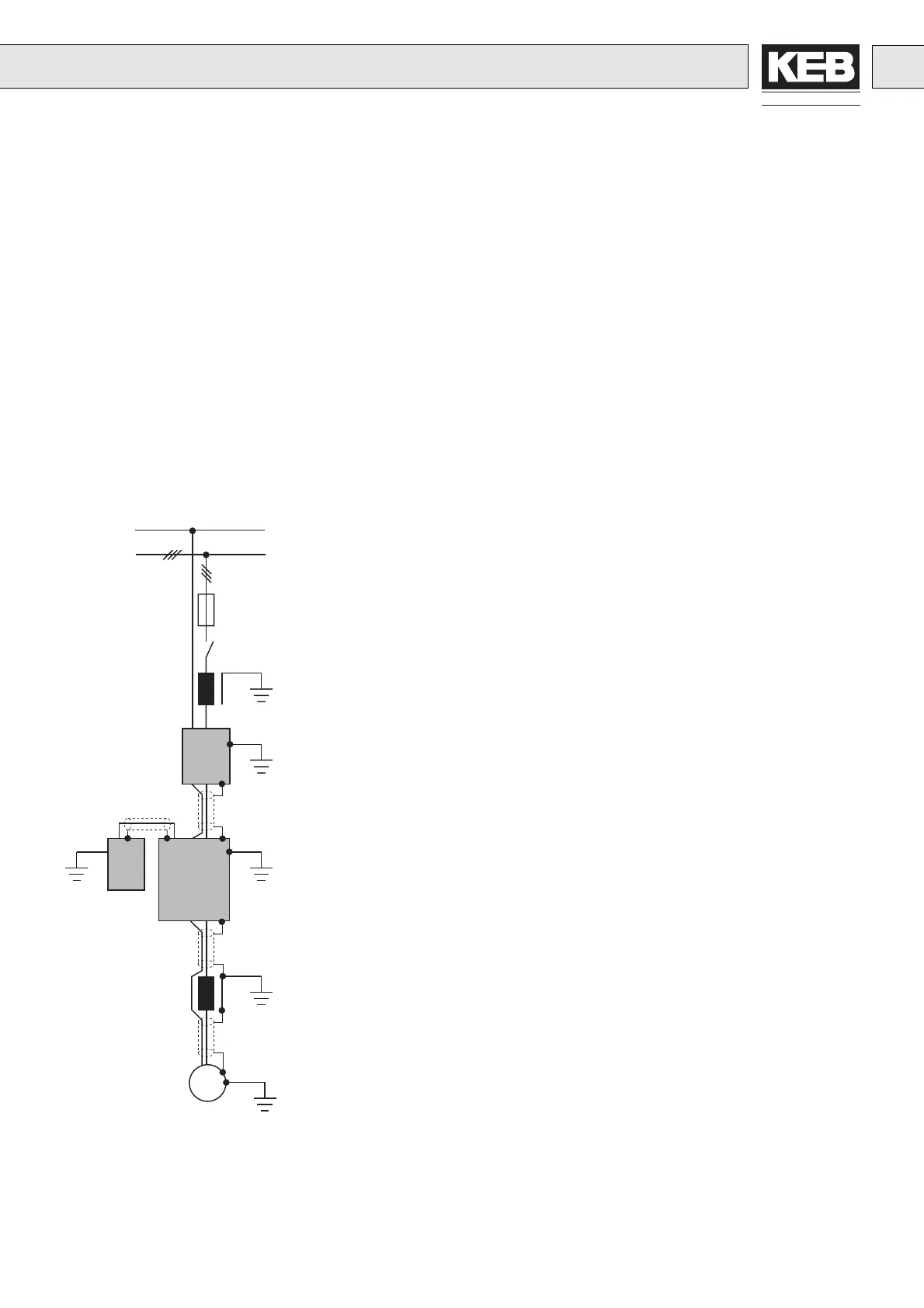
1. Mains Fuse
2. Main Protection
3. Line Reactor
4. Interference Suppression Filter
(if not already installed)
5. Inverter with Braking Resistor
6. Motor Choke or Output Filter
7. Motor
1
2
3
4
5
6
7
3.2 Installation
 Loading...