Do you have a question about the Kenmore Oasis 110.77082600 and is the answer not in the manual?
Explains safety precautions and warnings for dryer operation.
Details the format and meaning of model and serial numbers.
Shows where to find the model and serial number labels.
Outlines the one-year limited warranty terms and conditions.
Provides guidance on installing the dryer, including tools and parts.
Specifies necessary site conditions and clearances for dryer installation.
Details electrical supply needs and connection methods for electric models.
Explains proper grounding procedures for safe dryer operation.
Instructions for connecting power supply cords and direct wiring.
Specifies electrical needs and safety for gas dryer models.
Details requirements for connecting the gas supply line and connections.
Information on BTU rating adjustments for elevation.
Critical instructions for safe and effective dryer exhaust venting.
Guidance on vent parts, installation, and planning the system.
Steps for installing the dryer exhaust vent hood and connecting the vent.
Instructions for leveling the dryer and connecting the vent.
Instructions for changing the direction of the dryer door swing.
Final checks before operating the dryer, including starting and heat tests.
Basic operating instructions and safety warnings for using the dryer.
Step-by-step guide to start the dryer for the first time.
How to select and use automatic drying cycles based on load dryness.
How to select and use timed drying cycles with specific durations.
Instructions on how to pause, stop, or restart a drying cycle.
Advice for optimal drying, reducing wrinkles, and load handling.
Explanation of indicator lights and their meanings during operation.
Introduction to the different drying cycles available for the dryer.
Detailed descriptions of Auto Dry and Timed Cycles for various load types.
How to adjust cycle modifiers like dryness level and use the Air Dry feature.
Customizing cycles with options like drum light, damp signal, and wrinkle guard.
Adjusting preset dryness levels and using the dryer rack.
Diagrams showing the location of internal dryer components.
Detailed steps for removing console and control components.
Step-by-step guide to remove the moisture sensor assembly.
Instructions for accessing and removing the dryer's front panel and door switch.
Guide for removing the internal drum light and socket.
Procedure for removing the thermal fuse and outlet thermistor.
Steps to remove thermostats, thermal cutoff, and electric heater assembly.
Instructions for removing gas burner assembly, thermostats, and flame sensor.
Detailed steps for removing the dryer drum, belt, and rollers.
Procedure for removing the blower fan assembly on single motor models.
Steps to remove blower motor and fan on dual motor models.
Instructions for removing the drive motor and belt switch.
Procedure to test the door switch functionality using an ohmmeter.
How to test the thermal fuse and outlet thermistor for continuity and resistance.
Testing the high-limit thermostat, inlet thermistor, thermal cutoff, and electric heater.
Procedure to test the resistance of gas burner coils.
How to test the resistance of the burner ignitor.
Procedure to test the continuity of the flame sensor.
How to test the high-limit thermostat and thermal cutoff on gas models.
Procedure to test the resistance of the blower motor terminals.
How to test the continuity of the belt switch.
Testing motor windings, thermal overload, and centrifugal switch contacts.
List and explanation of error codes displayed by the dryer.
General checks and procedures for initiating diagnostic tests.
Steps to enter the dryer's diagnostic test mode.
Tests for door switch, moisture sensor, and console ID verification.
Reading inlet airflow and line voltage displays in diagnostic mode.
How to activate and perform the manual load test.
Common problems and their potential causes or tests.
Verifies continuity of power cord connections to the terminal block.
Checks if power is present and the machine control is functional.
Tests the wiring and components of the drive motor circuit.
Steps to diagnose why the dryer is not producing heat.
Checks the exhaust thermistor's resistance and temperature readings.
Checks continuity across the thermal fuse.
Checks continuity across the thermal cut-off.
Tests the gas valve coil for proper resistance.
Diagnoses issues with automatic cycles stopping too soon or running too long.
Troubleshoots issues with console indicators, beeps, and buttons.
Tests the door switch functionality and its connection to the control.
Customizing auto cycle dryness levels.
Steps for removing the front panel and drum assembly.
General steps for accessing the user interface and machine control electronics.
Detailed steps for removing the machine control electronics assembly.
Steps to remove the motor control electronics on dual motor models.
Detailed steps for removing the user interface assembly.
List and explanation of error codes specific to gas dryer models.
Schematic diagrams for electric dryer electrical systems.
Schematic diagram for the gas dryer electrical system.
Simplified wiring diagrams for motor and related components.
Simplified wiring diagrams for dual motor blower system.
Simplified wiring diagrams for gas dryer heating and valve systems.
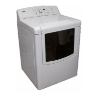
| Appliance Category | Dryer |
|---|---|
| Brand | Kenmore |
| Model Number | 110.77082600 |
| Type | Electric |
| Capacity | 7.0 cu. ft. |
| Color | White |
| Dryer Venting | Vented |
| Number of Temperature Settings | 5 |
| Wrinkle Prevention Option | Yes |
| End of Cycle Signal | Yes |
| Power Source | Electric |
| Voltage | 240 V |
| Amperage | 30 A |
| Width | 29 in. |
| Height | 43 in. |
| Control Type | Electronic |
| Weight | 120 lbs |
| Drying Cycles | Delicates, Heavy Duty, Normal, Quick Dry, Towels |