KRC-165
6
TEST MODE / ADJUSTMENT
1. How to enter the test mode
• Reset the unit while holding the Track Down key and preset
6 key.
• All indication segments go ON at the beginning of the test
mode.
2. How to release the test mode
• Simply reset the unit.
• (NOTE) The test mode is not canceled by ACC OFF, power
OFF, momentary power down or the panel off.
3. Contents
• Set the volume level to -10dB (which is shown as "30" on
the display).
• Loudness OFF.
• The BASS / TREBLE and BALANCE / FADER
controls can be set to the full boost / center / full cut and full
right / center / full left and full front / center / full rear
respectively.
• Sound coordination doesn't appear for the Audio mode feed.
• The inspection function of LCD
When all indication segments are ON, the segments can be
set to the following order respectively by pressing the Track
up key / Track down keys.
All indication segments ⇔ Odd segments (Common 1 part)
⇔ Even segments (Common 2 part) ⇔ Odd segments
(Common 3 part) ⇔ All indication segments
• When the unit is reset (backup turned on) while ACC is OFF
in test mode, the MUTE terminal goes off in 2 seconds.
Set the controls and switches as follows.
BALANCE : center position BASS : center position LOUDNESS : OFF
FADER : center position TREBLE : center position
ITEM TAPE
OUTPUT
SETTINGS
RECIEVER
SETTINGS
ALIGNMENT
POINTS
No.
HEAD
HEIGHT
HEAD
AZIMUTH
SCC-1659
TCC-153
10kHz
-
Connect an AC
voltmeter and
oscilloscope to
SP outputs.
TAPE PLAY
TAPE PLAY
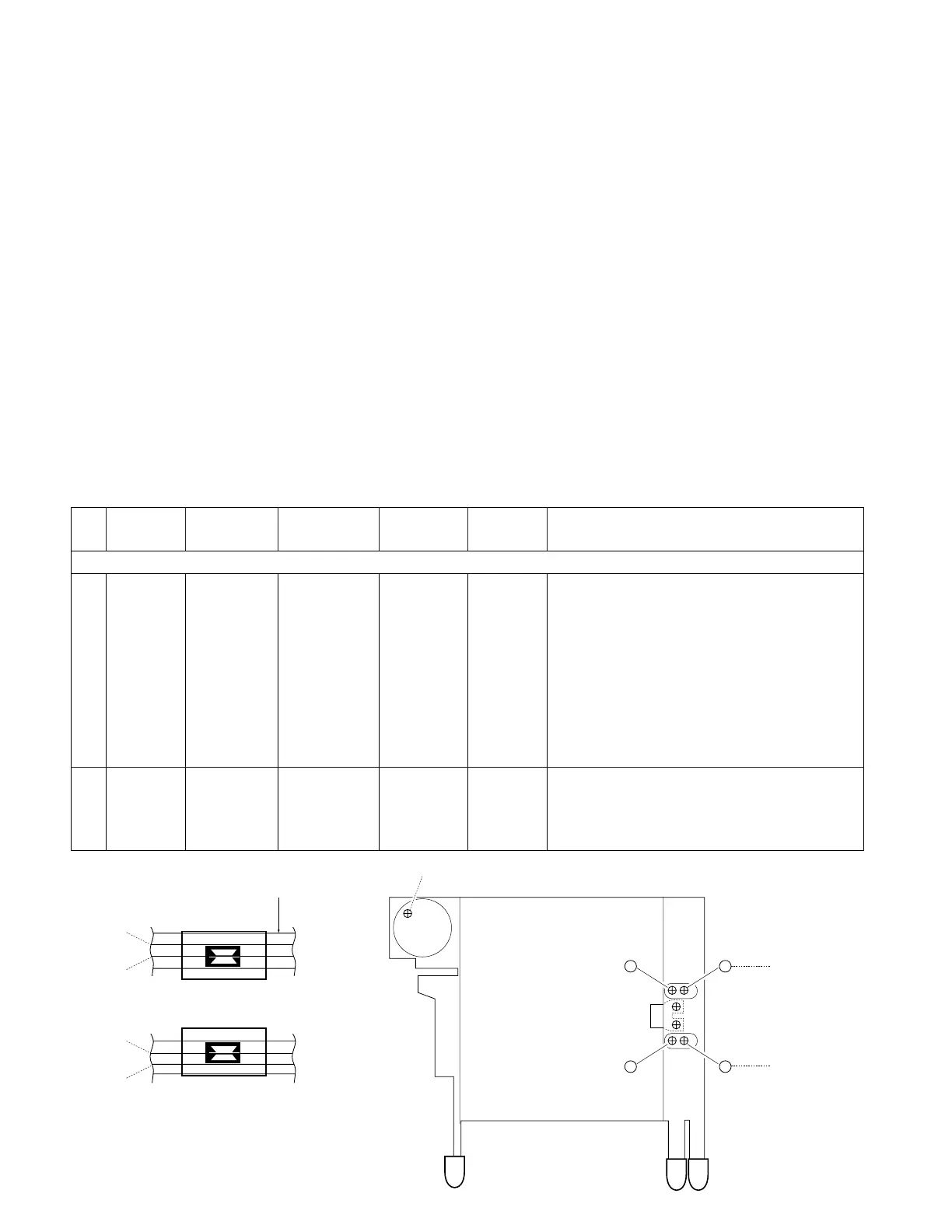
Head
Height
Screw
Head
Azimuth
Screw
ALIGN FOR
1) During FWD transport adjust
⁄F and ⁄F ' so that line A
of 2-LINE TAPE passes through the center of the
head shield plate (core center area)
2) During RVS transport adjust ⁄
R and ⁄R ' so that line B
of 2-LINE TAPE passes through the center of the
head shield plate (core center area)
3) After the alignment above, reverse the transport
direction and check the FWD alignment again. If it is
deviated, perform alignment again. (Tape used :
SCC-1659, manufactured by A-BEX)
Adjust the azimuth for each L ch/R ch or FWD/RVS
becomes maximum.
[1]
[2]
CASSETTE DECK SECTION
TEST MODE
ADJUSTMENT
 Loading...