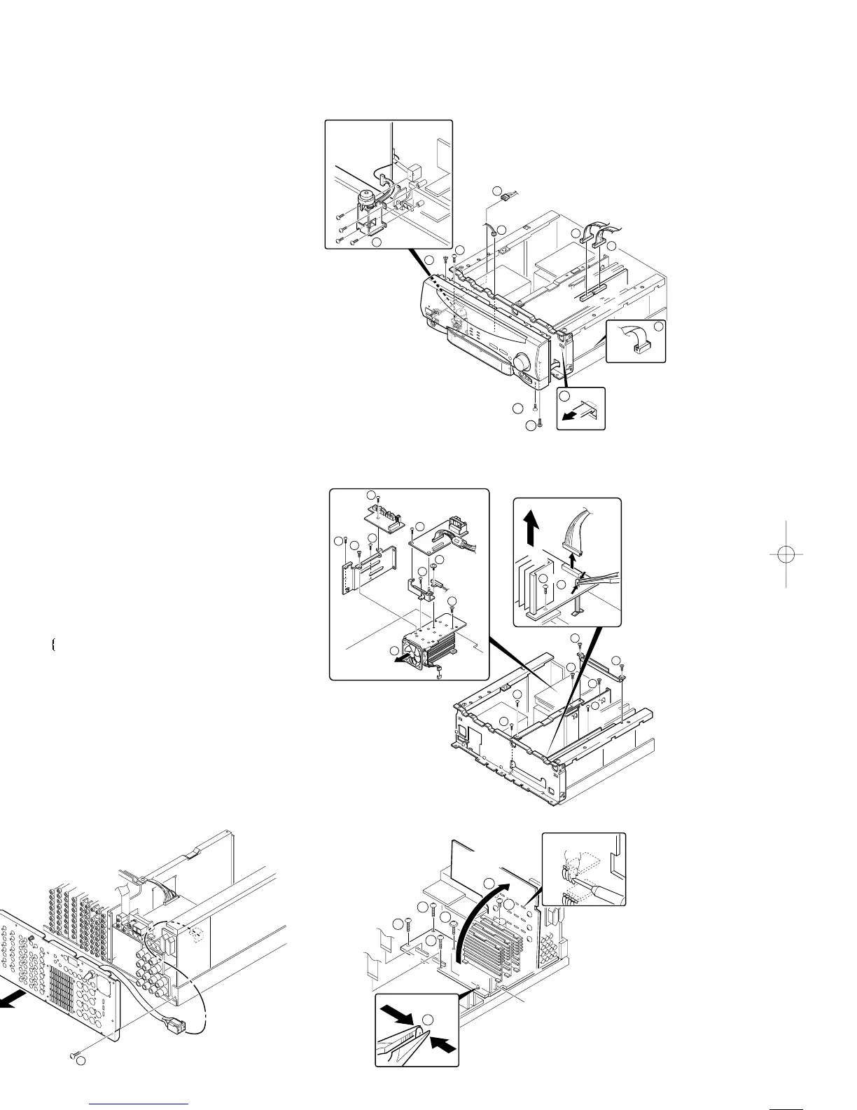
1. Take out the connectors (1) {X07,CN1/X13(CN7,CN8)} and
the AC connetor(2).
2. Take the lead (3) out of CN301 on X11(A/4) PCB.
3. Take out the screws (4) and (5).
4. The front panel can be separated by removing 2 hooks (6)
on the sub panel.
5. To separate the motor from the front panel, remove the
screws (7).
1. The rear panel can be separated by removing screws (1)
on the rear panel.
2. Take the AC connector out of CN2 on the X07(C/7).
3. To separate the chassis from bottom chassis, remove the
screws (2).
4. Remove CN21 and screws (3) on X13(C/5).
5. Remove screws (4 to 7).
6. The fan motor can be separated by removing screws (8)
and the connector (CN12) on X07 PCB.
7. Take the PCB
X25(B/9), X11(C/4)} out of X07.
8. To separate the main PCB (X07) from the bottom chassis,
remove screws (0).
9. Set up the PCB as figure (-).
10. Replace the defective transistors.
HOW TO REPLACE THE POWER TRANSISTOR.
HOW TO REMOVE THE FRONT PANEL AND THE MOTOR.
 Loading...