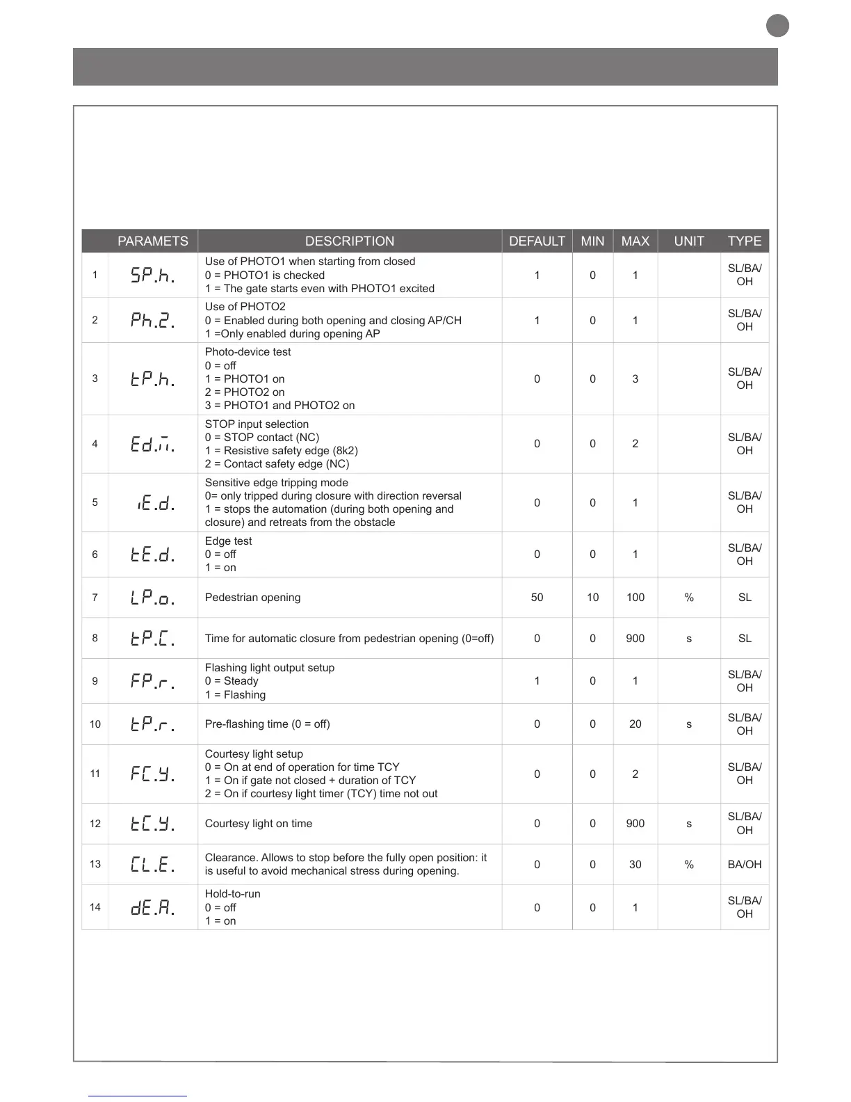
PARAMETS DESCRIPTION DEFAULT MIN MAX UNIT TYPE
1
SP.h.
Use of PHOTO1 when starting from closed
0 = PHOTO1 is checked
1 = The gate starts even with PHOTO1 excited
1 0 1
SL/BA/
OH
2
Ph.2.
Use of PHOTO2
0 = Enabled during both opening and closing AP/CH
1 =Only enabled during opening AP
1 0 1
SL/BA/
OH
3
tP.h.
Photo-device test
0 = off
1 = PHOTO1 on
2 = PHOTO2 on
3 = PHOTO1 and PHOTO2 on
0 0 3
SL/BA/
OH
4
Ed.m.
STOP input selection
0 = STOP contact (NC)
1 = Resistive safety edge (8k2)
2 = Contact safety edge (NC)
0 0 2
SL/BA/
OH
5
iE.D.
Sensitive edge tripping mode
0= only tripped during closure with direction reversal
1 = stops the automation (during both opening and
closure) and retreats from the obstacle
0 0 1
SL/BA/
OH
6
tE.D.
Edge test
0 = off
1 = on
0 0 1
SL/BA/
OH
7
LP.o.
Pedestrian opening 50 10 100 % SL
8
TP.C.
Time for automatic closure from pedestrian opening (0=off) 0 0 900 s SL
9
FP.r.
Flashing light output setup
0 = Steady
1 = Flashing
1 0 1
SL/BA/
OH
10
tP.r.
0 0 20 s
SL/BA/
OH
11
FC.Y.
Courtesy light setup
0 = On at end of operation for time TCY
1 = On if gate not closed + duration of TCY
2 = On if courtesy light timer (TCY) time not out
0 0 2
SL/BA/
OH
12
tC.Y.
Courtesy light on time 0 0 900 s
SL/BA/
OH
13
CL.E.
Clearance. Allows to stop before the fully open position: it
is useful to avoid mechanical stress during opening.
0 0 30 % BA/OH
14
de.a.
Hold-to-run
0 = off
1 = on
0 0 1
SL/BA/
OH
ADVANCED MENU allows the system to be further customised
by modifying parameters not accessible from the basic menu.
down for 5 seconds.
for the BASIC MENU.
SL= sliding gate
BA= barrier
N.B. Some default functions/display items may vary with respect to
the type of motor selected.

 Loading...