3
BOX BUILDING NOTES
Use 3/4” (1.9cm) or thicker MDF (medium density fi berboard) and seal the joints with silicone. Use the
“template” inside your L7R’s shipping carton to mark the mounting hole, then cut directly on the line.
These designs need internal bracing. Add triangular bracing between each of the larger unsupported
panels. See Figure 3.
All the cubic feet (L) measurements in this manual include the displacement of the woofer. For the vented
enclosures the displacement of the port must be calculated and added to the internal volume of the fi nal
design. Use the outer dimensions of the port and multiply “X x Y x Z”, convert to cubic feet, for example
the L7R12 vented Minimum design’s external port dimensions are, using 3/4” (1.9cm) MDF: [ (13.25” +
1.5” total MDF wall thickness) x (2.5” + 1.5” total MDF wall thickness) x 22.5”] x (1 ft
3
/ 1728 in
3
) = .77
ft
3
, and add this number to the internal volume of the enclosure, L7R12’s 1.75 ft
3
+ .77 ft
3
= 2.52 ft
3
. See
Figure 4. Due to the necessary length of these ports, you may want to fold the port along the bottom and
back walls. It will be impractical to use round ports for these designs.
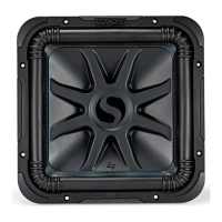
Figure 1
Series Wiring
Parallel Wiring
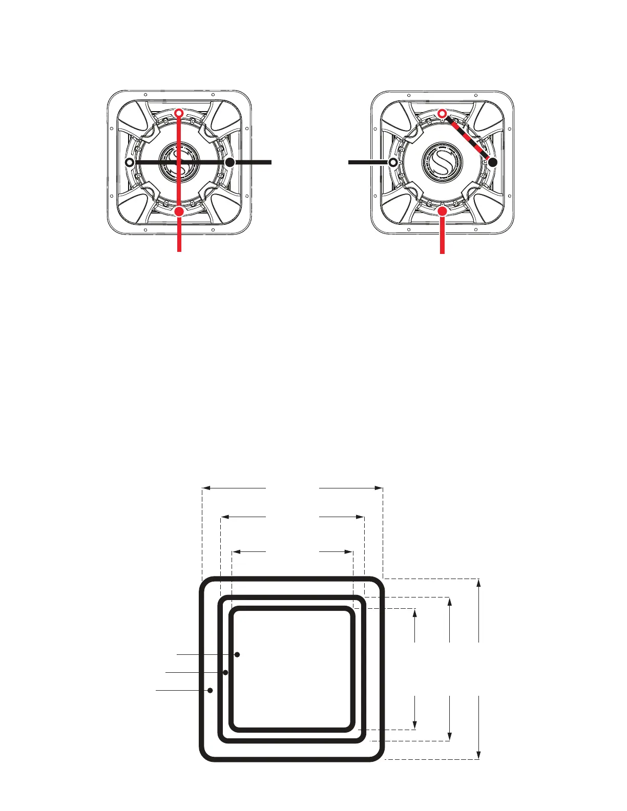
Figure 2
Cutout Dimensions
Dual 2Ω Voice Coils = 4Ω Load
Dual 4Ω Voice Coils = 8Ω Load
Dual 2Ω Voice Coils = 1Ω Load
Dual 4Ω Voice Coils = 2Ω Load
L7R10
L7R12
L7R15
13 3/4”
(34.9 cm)
11 1/16”
(28.1 cm)
9 5/16”
(23.7 cm)
13 3/4”
(34.9 cm)
11 1/16”
(28.1 cm)
9 5/16”
(23.7 cm)
Corner Radius:
L7R10 - 1-9/16” (3.9cm)
L7R12 - 1-13/16” (4.6cm)
L7R15 - 2” (5.1cm)
coil 1+
coil 2+
to amplifi er +
to amplifi er -
coil 2-
coil 1-
coil 1+
coil 2+
to amplifi er +
to amplifi er -
coil 2-
coil 1-
2018 L7R Rev F.indd 3 5/25/2018 1:03:27 PM
I
I
I
,.,
I
I
I
I
I
I
I
-
-
,-
-
-
I
I
I
-
--
-
-
~
~
-
-
_
_J
I
___
__
___
j
 Loading...