6. Installation / Activation Instructions
WIRING INSTRUCTIONS FOR AC HARNESS
!
CAUTION! TURN OFF THE MAIN POWER TO THE CIRCUIT
BEFORE WIRING THE ALARM.
• For alarms that are used as single station, DO NOT CONNECT THE RED
WIRE TO ANYTHING. Leave the red wire insulating cap in place to make
certain that the red wire cannot contact any metal parts or the electrical box.
• When alarms are interconnected, all interconnected units must be
powered from a single circuit.
• A maximum of 24 Kidde Safety devices may be interconnected in
a multiple station arrangement. The interconnect system should
not exceed the NFPA interconnect limit of 12 smoke alarms and/or
18 alarms total (smoke, CO, Smoke/CO Combination, heat detector,
etc.). With 18 alarms interconnected, it is still possible to interconnect
up to a total of 6 remote signaling devices and /or relay modules (see
below for details on interconnecting Kidde devices).
• The following models can be interconnected using the standard
AC wiring interconnect: i12020CA, i12020ACA, i12040CA,
i12040ACA, i12060CA, i12060ACA, i12010SCA, i12010SCOCA,
KN-SMFM-I-CA, KN-COB-ICB-CA, KN-COSM-IBCA, KN-COB-IC-CA,
KN-COSM-ICA, KN-COP-IC-CA, KN-COPE-ICA, P12040CA, Pi2000CA,
Pi2010CA, SM120X, CO120X, SLED177iCA, P4010ACLEDSCA,
P4010ACLEDSCOCA.
• The maximum wire run distance between the first and last unit in an
interconnected system is 305 m (1000’).
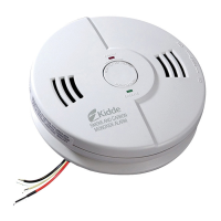
WIRES ON ALARM HARNESS CONNECTED TO
Black Hot side of AC line
White Neutral side of AC line
Red Interconnect lines (red wires) of other
units in the multiple station set up
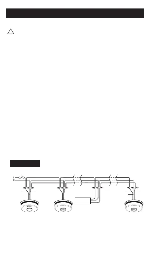
Interconnect Wiring Diagram
FIGURE 3
FUSE OR CIRCUIT BREAKER
REDBLACK
WHITE
REDBLACK
WHITE
First
Alarm
Additional
Alarm
Kidde Relay Module
SM120X, CO120X
or both
Additional
Alarm
Optional
Accessory
 Loading...