Fig.27
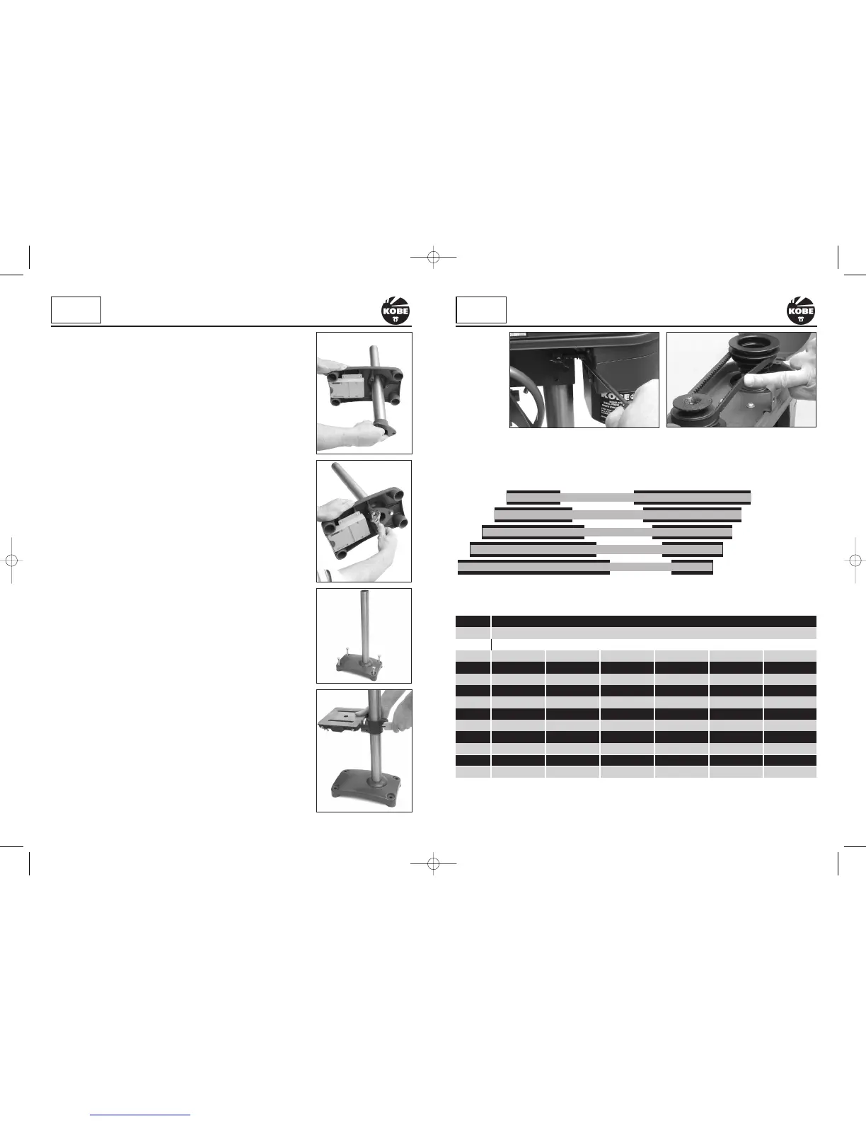
PULLEY ARRANGEMENT/SPINDLE SPEEDS
Fig.28
1 = 2650 rpm
2 = 1650 rpm
3 = 1220 rpm
4 = 850 rpm
5 = 580 rpm
Caution!
This packaging contains sharp objects. Take care when unpacking.
Remove the machine, together with the accessories supplied, from
the packaging. Check carefully to ensure that the machine is in good
condition and account for all the items listed on page 5 of this
manual. Also make sure that all the parts are complete. If any parts
are found to be missing or damaged, the Pillar Drill and its
accessories should be returned together in their original packaging to
your local Kobe agent.
Do not throw the packaging away, keep it safe throughout the
guarantee period, then recycle if possible, otherwise dispose of it by
the proper means. Do not let children play with empty plastic bags
due to the risk of suffocation.
LOCATING THE MACHINE
When determining where to locate or permanently fix the Pillar Drill,
consideration must be given to the following points:
Is there a suitable mains outlet socket near by.
If the machine is to be permanently mounted onto a bench is the
bench at a suitable height, strong and stable enough to carry the
weight of the machine plus items to be machined on it.
IDENTIFICATION/PREPARATION
Lift out the base plate, remove the protective paper and place the
base plate on a workbench or the floor.
Locate the chuck, chuck key, hexagonal key, telescopic guard and
place to one side for time being.
Lift out the worktable, head stock/motor assembly and the column,
remove the protective paper and place them onto the workbench.
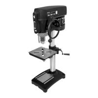
FITTING THE COLUMN
(Fig. 2 & 3)
Slide the column assembly into the base from the bottom. (Fig.2)
Insert the three hexagon head bolts supplied through the holes in the
triangular flange and into the corresponding holes in the base plate.
Tighten the three bolts into the base plate (Fig.3).
Do not over tighten as this could damage the cast base plate.
SECURING THE BASE PLATE
Select a suitable location for the Pillar Drill on the bench for mounting
the base plate.
A suitable mains supply socket must also be accessible for the plug.
Locate the base plate in the selected position. Select four suitable
length fixing bolts, nuts and washers (not supplied).
Using the base plate as a template, drill four holes in the bench with
a suitable drill bit. Insert the bolts, adding the nuts and washers
underneath or above depending on accessibility. Tighten the nuts
onto the bolts to secure the base plate onto the bench (Fig.4).
Do not over tighten as this could crack the cast base plate.
6
KOBE
INDUSTRIAL
POWER TOOLS
ASSEMBLY
Fig.2
Fig.3
Fig.4
11
KOBE
INDUSTRIAL
POWER TOOLS
SETTING UP & ADJUSTMENT
Fig.5
Fig.26
DRILLING SPEED CHART (GUIDE ONLY)
Material to be drilled
Size Steel Cast Iron Gun Metal Aluminum Plastics Wood
(mm) Drill Speed (rpm)
3 2500 2500 2500 2500 2500 2500
4 2500 2500 2500 2500 2500 2500
5 1750 2500 2500 2500 2500 2500
6 1750 2500 2500 2500 2500 2500
7 1250 1750 2500 2500 2500 2500
8 1250 1750 2500 2500 2500 2500
9 900 1250 1750 2500 2500 2500
10 900 1250 1750 1750 2500 2500
11 600 900 1250 1750 1750 2500
12 600 900 1250 1750 1750 1750
13 600 600 900 1250 1750 1750
Fig.29
Drill
KBE-271-2030K_Instructions.qxd 09/06/2009 09:20 Page 6
 Loading...