Fig.9
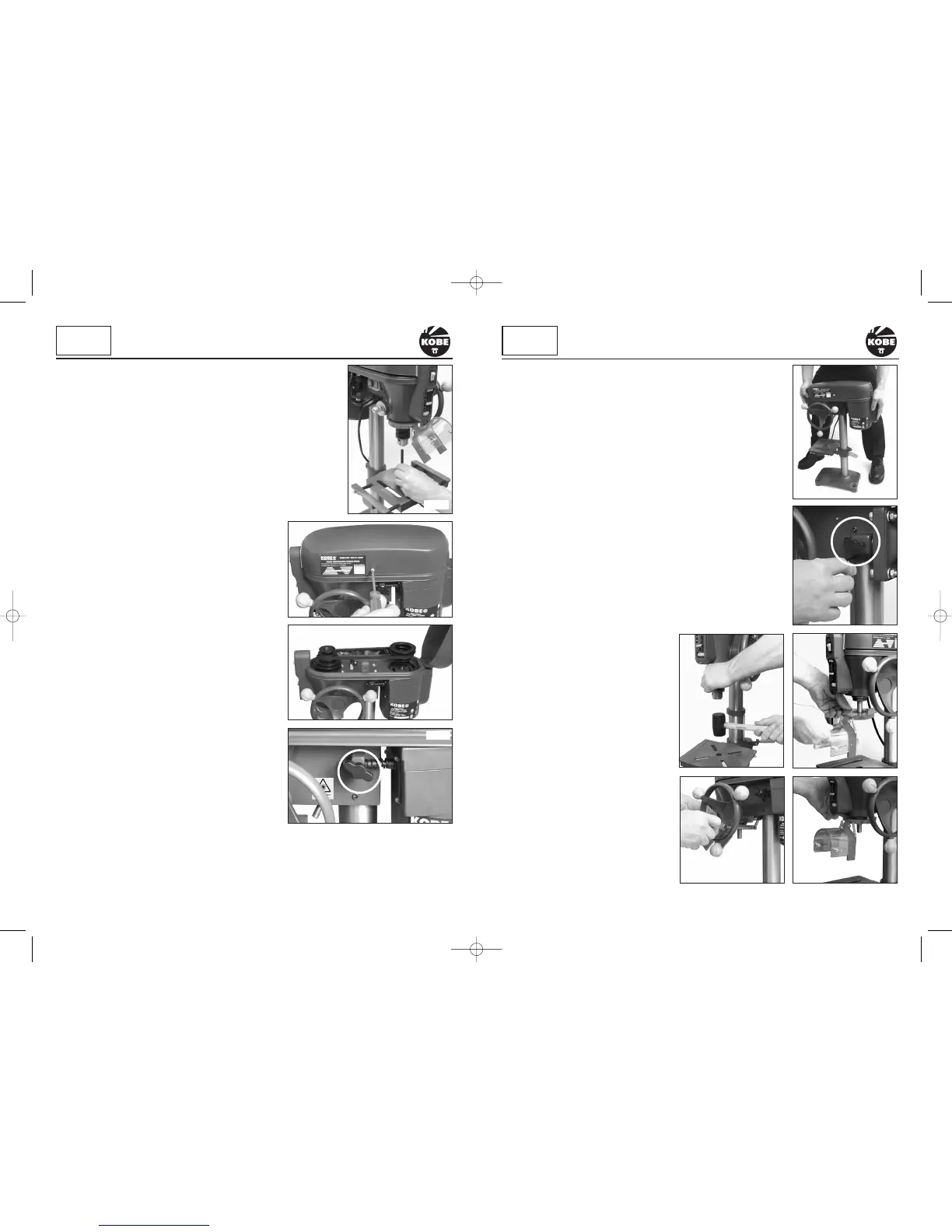
FITTING THE TABLE/SUPPORT ARM ASSEMBLY
Locate the table/support arm assembly (Fig.1) . Lower the table/
support arm assembly over the top of the column and line up with
the base plate. Tighten the support arm column clamp (Fig.5)
FITTING THE HEAD STOCK AND MOTOR ASSEMBLY
Locate the two grub screws in the side of the drill head stock and
motor assembly (Fig.7). Using a hexagonal key slacken the two grub
screws. Lift the drill head stock and motor assembly onto the
column. Make sure that it slides down and locates fully on the
column. Position the head stock and motor assembly, with the drill
head aligned over the table and base plate (Fig.6). Tighten the two
grub screws (Fig.7) to secure the head stock and motor assembly
into place. Retain the hexagon key for future adjustments.
FITTING THE CHUCK
The chuck has a taper fitting, simply place it onto the spindle adaptor
and tap with a soft rubber mallet (Fig.8). This is enough to secure in
it place and it should be tight enough. To make doubly sure, place a
piece of wood on the table and wind the manual feed handle to bring
the chuck down onto the wood pressing the chuck tighter onto the
spindle adaptor.
To remove, tap the chuck in a downward
motion with a soft mallet.
FITTING THE
TELESCOPIC GUARD
Position the clear plastic shield into the
red collar and secure in place with the two
small cross head screws. Place over the
chuck and locate onto the drill head collar
(Fig.9). Tighten the cross-head clamping
screw but don’t over tighten as this may
break the plastic body (Fig.10). Check that
the guard lifts easily and stays lifted to
change drills/cutting tools (Fig.11).
10
KOBE
INDUSTRIAL
POWER TOOLS
ASSEMBLY continued
7
Fig.6
USING THE 3 JAW CHUCK
Select the drill bit required, open the jaws and insert the drill shank centrally
into the chuck (Fig. 22). Rotate the chuck by hand until the jaws grip the drill
bit. The chuck has three holes around the chuck body. Using the chuck key,
exert an even torque to tighten, moving from one hole to the next until all
three holes have been covered. Do not over tighten otherwise you will have
difficulty removing the drill bit.
CHANGING THE SPINDLE SPEED
Unscrew the cross head screw securing the pulley guard casing
(Fig.23). Lift open the casing to reveal the pulley system (Fig.24).
Determine the spindle speed required using (Fig.29) which shows
drill sizes against material types. Identify the pulley
arrangement that gives the nearest spindle speed to
that required by referring to the drill pulley
configurations (Fig. 28).
Slacken the wing nut located on the right side of the
drill head casting (Fig.25).
This will release the tension on the drive belt. The
motor, situated at the rear of the machine can now slide
on the slide bar. Push it towards the front to enable belts
to be removed and re-positioned to achieve your required
speed setting.
To move the drive belts to the desired pulley
arrangement. Push the belt on the largest drive spindle
pulley towards the next smallest pulley and at the
same time rotate the drive spindle by hand until the
drive belt locates onto the next smallest pulley (be
careful not to trap your fingers between the belt and
pulley). Repeat this procedure until the desired pulley
arrangement has been achieved.
BELT TENSION
When the desired pulley arrangement has been
achieved, tension the drive belt by inserting a large
screwdriver or small pry bar between the the drill head
casting and the motor mounting (Fig.26). Lever the
motor mount away from the casting and tighten the wing nut. To check that the correct tension
has been achieved, press your finger onto the centre of the drive belt (Fig.27). The drive belt
should move approximately 13mm. Once this has been achieved, re-tighten the wing nut to lock
the motor slide bar in position.
Fig.7
KOBE
INDUSTRIAL
POWER TOOLS
SETTING UP & ADJUSTMENT
Fig.8
Fig.11
Fig.10
Fig.23
Fig.24
Fig.22
Fig.25
KBE-271-2030K_Instructions.qxd 09/06/2009 09:20 Page 7
 Loading...