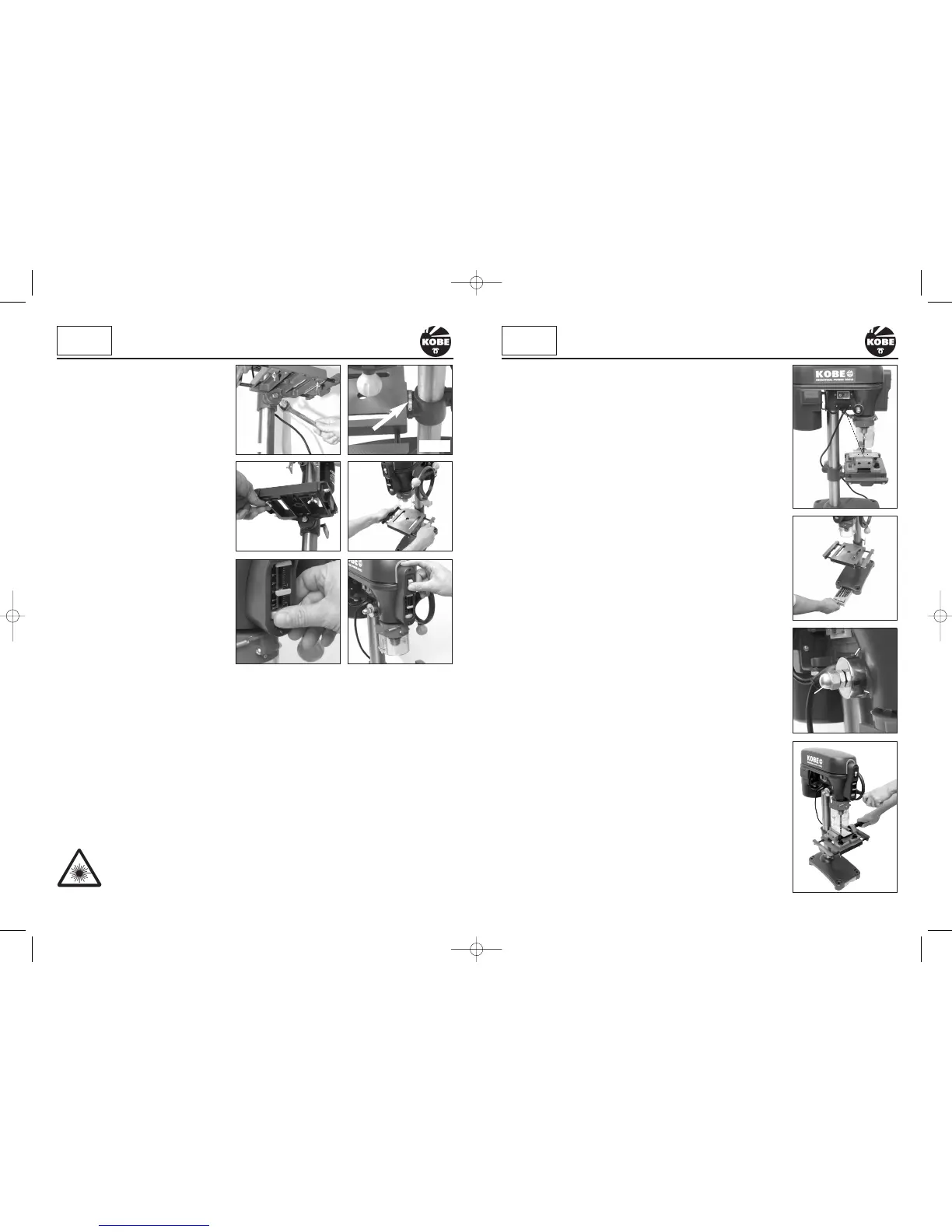
INTEGRAL BIT STORAGE TRAY
Conveniently located in the base of the Pillar Drill is a handy storage tray
for keeping your bits organised and close at hand. (Fig.19).
QUILL SPRING ADJUSTMENT
WARNING:
The quill spring is under extreme tension.
The quill spring is located in a chrome housing on the opposite side of the
feed shaft boss and returns the spindle to its uppermost position.
Adjustment is normally only required after many hours of use when it fails to
return the spindle to its uppermost position. With the spindle in its
uppermost position it can be seen that the chrome cover has a total of
three notches (Fig.20b) cut into the edge that align with the cast body of the
head stock. One of these notches is located over a cast peg (Fig. 20a) that
is part of the main casting.
WARNING: Before slackening the lock nuts ensure that the chrome
housing is held securely with a suitable grip or wrench. If not held
securely the quill spring will fully uncoil.
Carefully slacken the lock nuts (Fig.20c) only enough to allow the chrome
housing to be pulled out far enough to just clear the cast peg (Fig. 20a)
while holding the chrome cover with suitable grips. The spring is still under
tension and will try to uncoil as soon as it is released so be sure to resist
the torque. As soon as the chrome housing is able to clear the cast peg,
turn the chrome housing in an anti-clockwise direction until the next notch
locates onto the peg. While holding the chrome housing in this position
tighten the lock nuts. Do not over tighten otherwise you will damage the
chrome cover.
USING A MACHINE VICE
WARNING: The drill should never be used without the work piece being
securely held in a machine vice or clamped directly to the drill table.
The drill table is designed to accept a variety of machine vices which can be
fastened directly to the drill table; (Fig.21) gives an indication as to the type
of machine vice required.
Always secure the vice to the table with bolts, washers and nuts. If the drill
jams into the work piece, an unsecured machine vice will spin out of control
causing the drill to snap and possibly injure the operator.
ADJUSTING THE TABLE HEIGHT
To adjust the table height, slacken the
clamping lever at the rear of the table
support assembly (Fig. 5).
Slide the table up or down to desired
height. When the desired height has been
achieved, do not forget to re-secure the
clamping lever.
TILTING THE TABLE ± 45
°
Locate the securing bolt underneath the
table (Fig.12). With a suitable spanner or
wrench loosen the bolt. On the table
support assembly casting there is a
graduated 0 - 45° scale (Fig.13). Set the
table to the required angle and re-tighten
the bolt.
NOTE: The graduated scale is for guidance
only. We recommend the use of an
engineers protractor when setting any
angles
ADJUSTING THE TABLE WIDTH
Locate and loosen the wing nuts under the
table (Fig.14) and pull the side plates away from the main table (Fig.15). This will allow support for
larger machine vices and pieces of work (Fig.21). Once the side plates are in place don’t forget to
re-tighten the wing nuts.
SETTING THE DEPTH STOP
This facility is useful if a number of uniform depth holes are required in a work piece. The depth
stop is located on the front of the drilling head. To adjust, turn the thumb wheel (Fig.16) to the right
to increase the depth of travel of the drilling head or to the left to decrease the depth of travel.
LASER GUIDE
Located under the drilling head is a laser guide which is switched on using the on/off switch
located on the front of the drilling head above the depth stops (Fig.17). It provides target cross-
hairs (Fig.18) which once set on your first workpiece of a batch will facilitate the accurate
placement of subsequent pieces.
This Class 2 laser can potentially cause severe damage to eyes.
Never look directly into the laser beam or point the laser beam at people either
directly or indirectly through reflective surfaces.
8 9
Fig.14
Fig.16
Fig.15
Fig.20
Fig.19
KOBE
INDUSTRIAL
POWER TOOLS
SETTING UP & ADJUSTMENT
KOBE
INDUSTRIAL
POWER TOOLS
SETTING UP & ADJUSTMENT
Fig.12
Fig.13
Fig.17
Fig.18
20c
20a
20b
Fig.21
 Loading...