TP-6515 10/07 13Section 2 Operation
Section 2 Operation
2.1 Prestart C hecklist
To ensure continued satisfactory operation, perform the
following checks or inspections before or at each
startup, as designated, and at the intervals specified in
the service schedule. In addition, some checks require
verification after the unit starts.
Air Cleaner. Check for a clean and installed air cleaner
element to prevent unfiltered air from entering the
engine.
Air Inlets. Check for clean and unobstructed air inlets.
Battery. Check for tight battery connections. Consult
the battery manufacturer’s instructions regarding
battery care and maintenance.
Exhaust System. Check for exhaust leaks and
blockages. Check the muffler condition and check for
tight exhaust system connections.
Inspect the exhaust system components for cracks,
leaks, and corrosion.
D Check for corroded or broken metal parts and replace
them as needed.
D Check that the exhaust outlet is unobstructed.
Oil Level. Maintain the oil level at or near, not over, the
full mark on the dipstick.
Operating Area. Check for obstructions that could
block the flow of cooling air. Keep the air intake area
clean. Do not leave rags, tools, or debris on or near the
generator set.
2.2 Exercising Generator Set
Operate the generator set without load once each week
for 20 minutes. If the generator set is not connected to
an automatic transfer switch (ATS) with an exercise
option, exercise the unit in the presence of an operator.
The operator should perform all of the prestart checks
before starting the exercise procedure. Start the
generator set according to the starting procedure in the
controller section of this manual. While the generator
set is operating, listen for a smooth-running engine and
visually inspect the generator set for fluid or exhaust
leaks. Check the air inlets and outlets and remove any
items restricting the air flow.
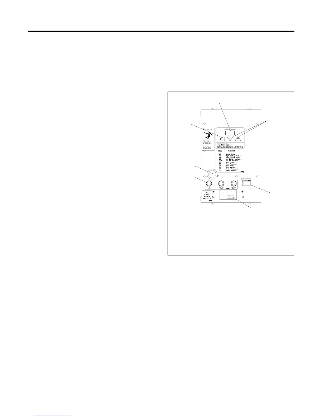
2.3 ADC-RES Controls and
Indicators
Figure 2-1 illustrates the ADC-RES user interface and
other items on the generator set junction box.
Figure 2-3 describes the ADC-RES c ontrols and
indicators.
xxx
1. Select button (use for setup and adjustment only)
2. LED display
3. Up and down arrow buttons
4. Generator set master switch
5. Line circuit breaker
6. Fuses
7. RS-232 connector (for application program upgrade)
2
1
4
3
5
6
6
Figure 2-1 ADC-RES Controls
2.3.1 LED Display
The LED display is activated by a start or RUN
command as follows:
D Move the master switch to RUN.
D With the master switch in AUTO, send a remote start
command (close the remote start contact across
leads 3 and 4).
The LED display indicates generator set status as
shown in Figure 2-3. When the generator set is running,
engine runtime hours are shown unless the arrow

 Loading...


