TP-6728 10/1116 Section 2 Operation
2.3.1 Controls and Indicators
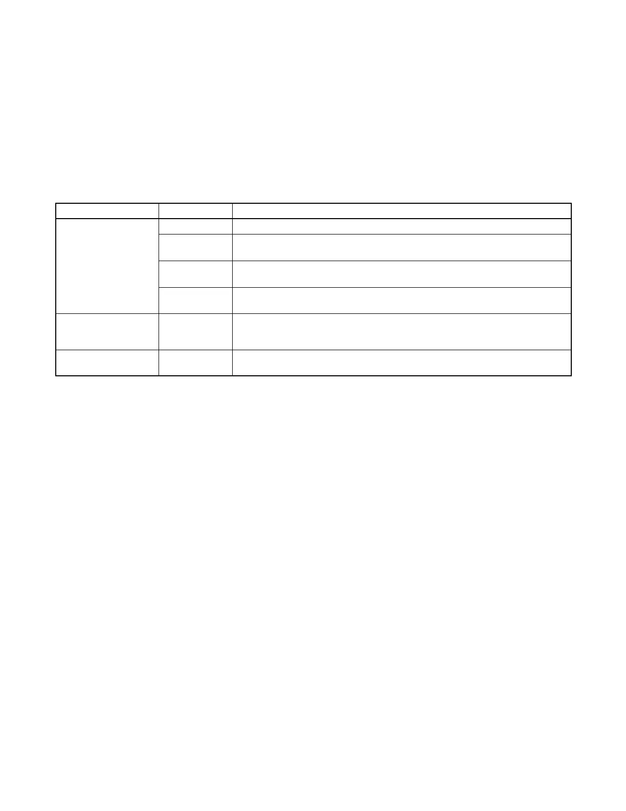
Figure 2-2 describes the controls and indicators located
on the controller . The LED display indicates generator set
status as shown in Figure 2-2. The display is active when
the master switch is in the RUN or AUTO position and
remains active until the generator set master switch is
moved to the OFF/RESET position or the power to the
controller is removed. If the factory-installed continuous
power mode jumper has been disconnected, the LED
display turns off 48 hours after the generator set
shutdown. See Section 2.3.6.
The buttons on the controller keypad are used only for
system configuration and adjustment. The ADC 2100 is
factory-set and should not require configuration or
adjustment under normal operating conditions. If the
generator set is reconnected to a different voltage
and/or frequency, refer to an authorized Kohler
distributor/dealer for system configuration and
adjustment instructions.
Control or Indicator Item Description
LED display
Runtime hours Displays total generator set runtime hours.
Crank indication Displays CC_1, CC_2, or CC_3 to indicate the first, second or third attempt to
start the engine. The last digit flashes during the crank cycle rest periods.
Fault codes Flashes a 2- or 3-letter fault code to indicate various fault conditions. See
Section 2.3.4.
Software
version
See the Generator Set Installation Manual.
Keypad Select and
arrow buttons
The keypad is used for controller setup and adjustment only. Have setup and
adjustments performed only by an authorized distributor/dealer. The setup and
adjustment functions are password-protected.
Generator set master
switch
Three-position
switch
Switch functions as the generator set operation and controller reset switch.
Figure 2-2 ADC 2100 Controls and Indicators
2.3.2 Starting Generator Set
The following procedures describe the actions required
to start the generator set.
Local Starting.
Move the generator set master switch to the RUN
position. The ADC 2100 attempts to start the generator
set in three crank cycles (crank cycle time is
pre-programmed). If the generator set does not start in
three attempts, the system shuts down on an overcrank
fault.
Auto (Automatic) Starting.
Move the generator set master switch to the AUTO
position to allow startup by an automatic transfer switch
(ATS), remote start/stop switch or remote digital gauge.
A remote start/stop switch or digital gauge can be
connected to the customer interface connection (P21
connector, leads 3 and 4). The generator set crank
cycle starts when the remote switch or engine start
contacts on the ATS contacts close.
The ADC 2100 attempts to start the generator set in
three crank cycles (crank cycle time is preprogrammed).
If the generator set does not start in three attempts, the
system shuts down on an overcrank fault.
2.3.3 Stopping Generator Set
The following procedures describe the actions required
to stop the generator set.
Local Stopping
1. Run the generator set with no load for at least
2 minutes to allow the engine to cool down.
2. Move the generator set master switch to the
OFF/RESET position. The engine stops.
Auto (Automatic)
Stopping
With the generator set master switch in the AUTO
position, open the remote start/stop switch contacts or
engine start contacts on the ATS to signal the generator
set to stop.
 Loading...


