TP-6519 8/17 Appendix 95
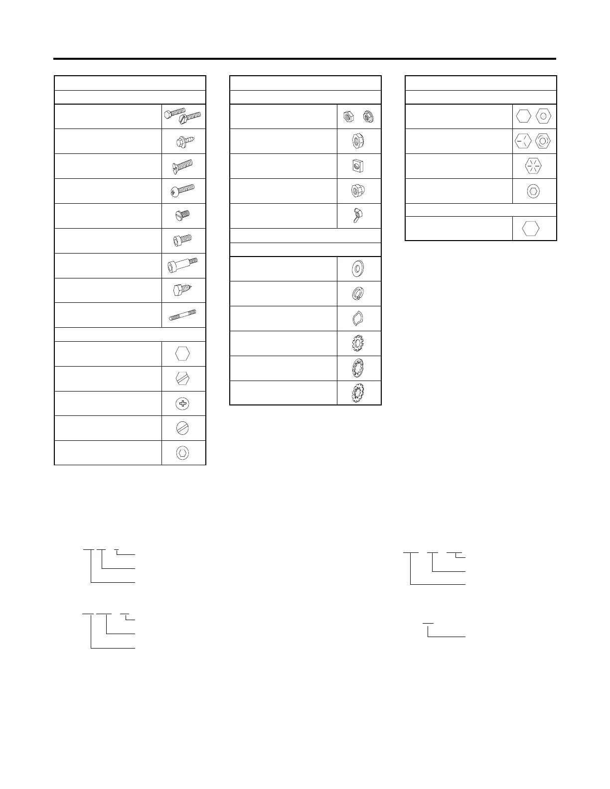
Appendix D Common Hardware Identification
Screw/Bolts/Studs
Head Styles
Hex Head or Machine Head
Hex Head or Machine Head
with Washer
Flat Head (FHM)
Round Head (RHM)
Pan Head
Hex Socket Head Cap or
Allent Head Cap
Hex Socket Head or Allent
Head Shoulder Bolt
Sheet Metal Screw
Stud
Drive Styles
Hex
Hex and Slotted
Phillipsr
Slotted
Hex Socket
Nuts
Nut Styles
Hex Head
Lock or Elastic
Square
Cap or Acorn
Wing
Washers
Washer Styles
Plain
Split Lock or Spring
Spring or Wave
External Tooth Lock
Internal Tooth Lock
Internal-External Tooth Lock
Hardness Grades
American Standard
Grade 2
Grade 5
Grade 8
Grade 8/9 (Hex Socket
Head)
Metric
Number stamped on
hardware; 5.8 shown
5.8
Allent head screw is a trademark of Holo-Krome Co.
Phillipsr screw is a registered trademark of Phillips Screw Company.
Sample Dimensions
1/4-20 x 1
Major Thread Diameter In Fractional Inches Or Screw Number Size
Length In Inches (Screws and Bolts)
Threads Per Inch
American Standard (Screws, Bolts, Studs, and Nuts)
Metric (Screws, Bolts, Studs, and Nuts)
M8-1.25 x 20
Major Thread Diameter In Millimeters
Length In Millimeters (Screws and Bolts)
Distance Between Threads In Millimeters
9/32
x5/8x 1/16
Plain Washers
Internal Dimension
Thickness
External Dimension
Lock Washers
Internal Dimension
5/8