42 TP-7044 6/23
Each relay provides one set of SPST contacts for field connection of customer supplied indicators or alarms. Contacts are rated
for a maximum resistive load of 10A at 120VAC.
The fifteen-relay dry contact board has four digital inputs and two analog inputs. There are fourteen programmable relay outputs
and one common fault relay output.
The relay contacts (K1 to K14) are rated:
• 10 amp @ 120 VAC
• 10 amp @ 28 VDC (max.)
• 0.01 amp @ 28 VDC (min.)
The common fault relay contact (K15) is rated:
• 500 mA @ 125 VAC
• 2 amp @ 30 VDC
2.13.1 Controller Fault Diagnostics
Figure 15 provides descriptions of possible system events and their types—warning, shutdown, status, and notice.
Warnings show a yellow warning lamp and sound an audible alarm to signal an abnormal condition. A warning does not shut
down the unit but indicates attention is required. Shutdowns show a red fault lamp, sound an audible alarm, and stop the
generator set. Statuses do not require user interaction but are part of the event history. Notices are used for controlling outputs
and notifying the user of the operating status. Notices are NOT part of the event history.
The default selection time delays and digital outputs are factory set and adjustable. Some data entries require using a PC and
SiteTech™ software.
Note:
Always identify and correct the cause of a fault shutdown before resetting the controller.
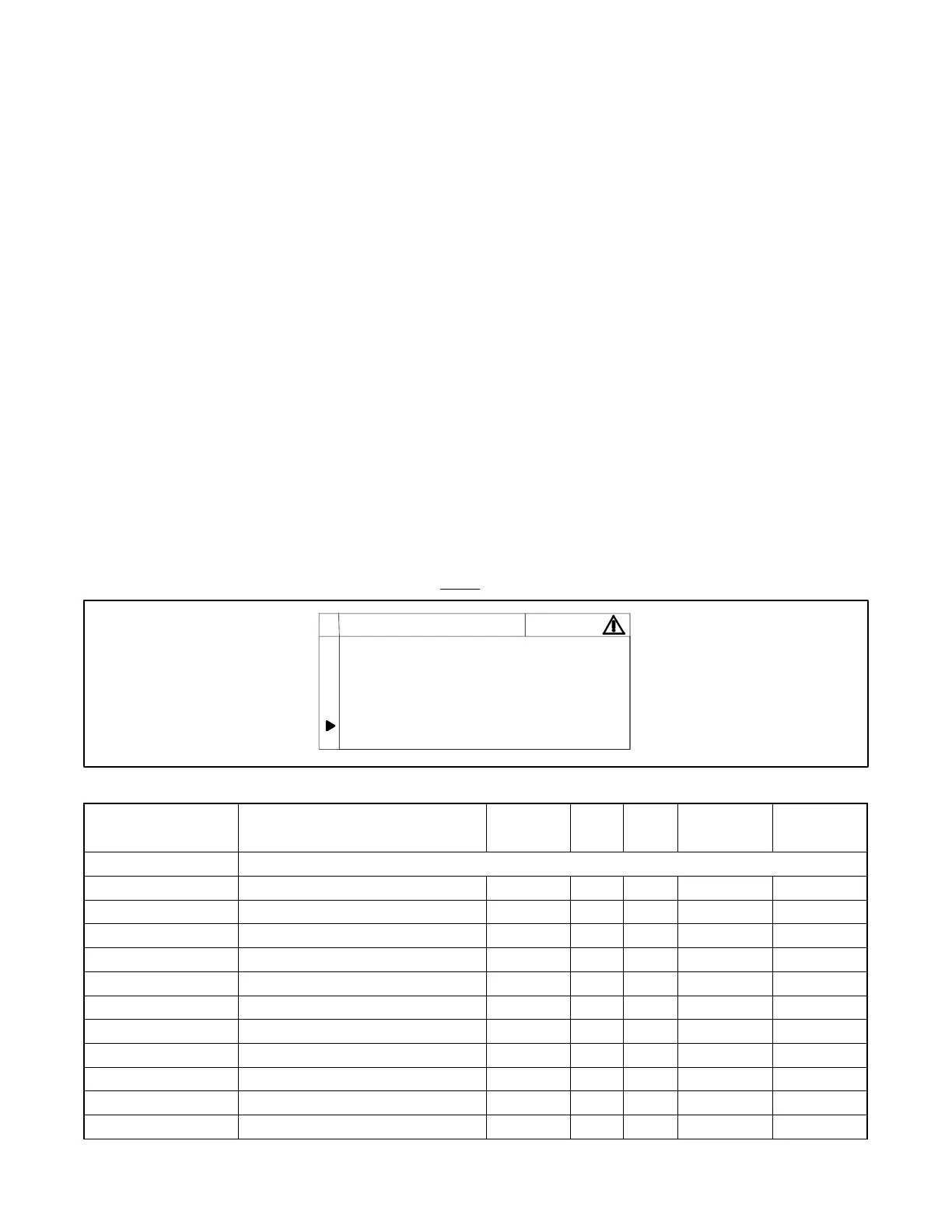
Figure 14 Event Screen Capture (Example)
01/02/2013 11:40:31 AM
Parameter Value Abnormal: Warning
PARAMETER: GEN BATTERY VOLTAGE
FMI: High
Event 4 or 4
PRESS OFF TO RETURN TO MAIN MENU
 Loading...