TP-6109 6/03 3Section 1 Specifications
Section 1 Specifications
1.1 Introduction
The specification sheets for each generator set provide
specific generator and engine information. Refer to the
respective specification s heet for data not supplied in
this manual. Consult the generator set service manual,
installation manual, engine operation manual, and
engine service manual for additional specifications.
1.2 Specifications
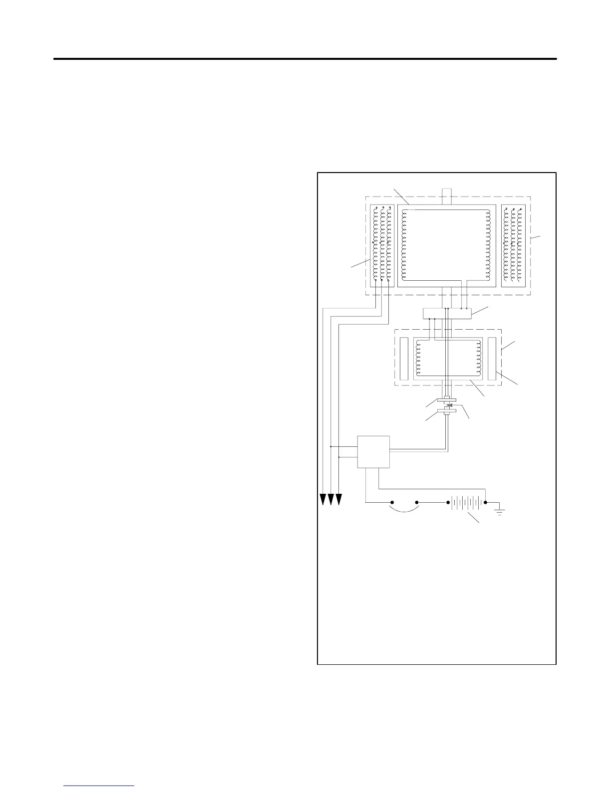
The alternator is a 4-pole, rotating-field unit with a
brushless, permanent-magnet-generator (PMG)
excitation system. The generator set excitation system
uses a permanent-magnet exciter with a
silicon-controlled rectifier (SCR) assembly that controls
the amount of DC current supplied to the generator field.
The voltage regulator sends a signal to the SCR
assembly through an optical coupling. The voltage
regulator bases the signal on engine speed and
generator output voltage. The signal turns a stationary
light-emitting diode (LED) on or off. The LED is mounted
on the end bracket opposite a photo transistor board
that rotates on the shaft. The photo transistor receives
the signal from the LED and signals the SCR assembly
to turn on or off. See Figure 1-1.
PMG, Fast-Responset II generator sets offer the
following advantages:
D The voltage recovery period of this type of generator
is several times faster than the conventional PMG
generators because the generator set does not have
to contend with the inductance of the 2
nd
exciter field.
D Better recovery characteristics than static-excited
generators because the system doesn’t draw
excitation power from the generator output voltage.
D The inherent ability to support short-circuit current
and allow system coordination for tripping
downstream branch circuit breakers.
The PMG exciter system changes the level of exciter
current to the main field within 0.05 seconds of a load
change.
For the duration of a short circuit in the load circuit(s), the
output voltage drops and the amperage momentarily
rises to 200--300% of the generator set’s rated current,
and 200--300% for the duration of the short circuit. The
SCR assembly sends full exciter power to the main field
and the generator sustains up to 300% of rated current.
The sustained high current causes the correspondingly
rated load circuit fuses/breakers to trip. The safeguard
breaker kit collapses the generator set’s main field
during a sustained heavy overload or short circuit.
1
2
3
4
6
7
8
9
10
11
12
13
5
TP-5353-1
1. Field
2. Main generator/alternator
3. SCR assembly
4. Exciter generator/alternator
5. Exciter field magnets
6. Exciter armature
7. Optical coupling
8. Starting battery
9. Safegaurd breaker (optional)
10. AC voltage regulator
11. LED board
12. Photo transistor board
13. Stator
Figure 1-1 Alternator Schematic
 Loading...

