TP-6773 5/12a 49Section 8 Reconnection
7685
11 10 12 9
15 14 16 13
L2
L3
To Generator
Set
To Shore
Power
To Load
4-Wire, 3-Phase Generator Sets
L0
3241
L1
L2
L3
L0
L1
L2 L3 L0L1
Kraus Naimler/American Solenoid
I-940
Figure 8-7 Marine Manual (Ship-to-Shore) Transfer
Switch, continued
8.3 Twelve-Lead Reconnection
The reconnection procedure details voltage
reconnections only. If the generator set requires
frequency changes, adjust the governor and voltage
regulator. See the generator set service manual for
information regarding frequency adjustment.
The following information illustrates the reconnection of
twelve-lead generator sets. In all cases, conform to the
National Electrical Code (NEC).
Reconnect the stator leads of the generator set to
change output phase or voltage. Refer to the following
procedure and connection schematics. Follow all safety
precautions at the front of this manual and in the text
during the reconnection procedure.
NOTICE
Voltage reconnection. Affix a notice to the generator set after
reconnecting the set to a voltage different from the voltage on
the nameplate. O rder voltage reconnection decal 246242
from an authorized service distributor/dealer.
Twelve-Lead Reconnection Procedure
1. Place the generator master switch in the OFF
position.
2. Disconnect generator set engine starting battery,
negative (--) lead first.
3. Disconnect power to battery charger, if equipped.
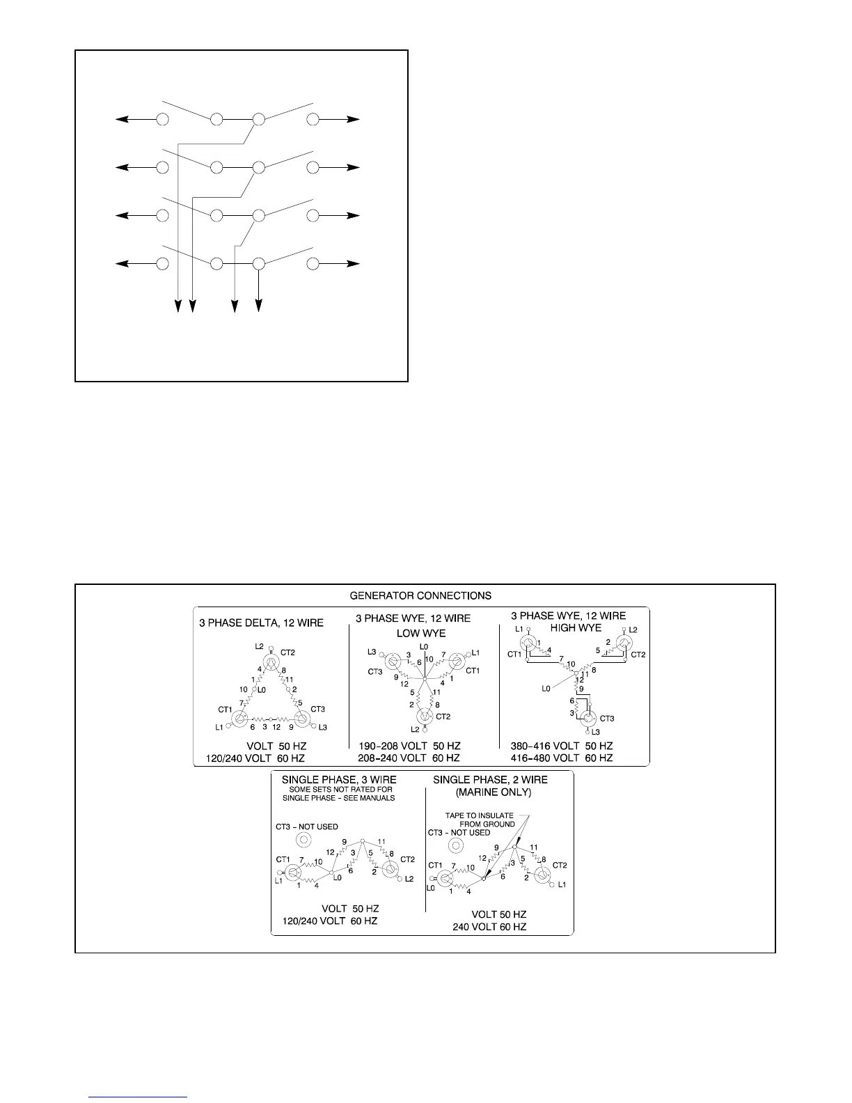
4. Use Figure 8-8 to determine the generator set
voltage configuration. Note the original voltage
and reconnect the generator set as needed.
EM-250000
Note: Current Transformers (CTs) are not used on all sets. CT dot or “HI” toward generator.
115/230
115/230
230
Figure 8-8 Generator Reconnection
 Loading...


