TP-6772 2/14b 13Section 1 Service Views
Section 1 Service Views
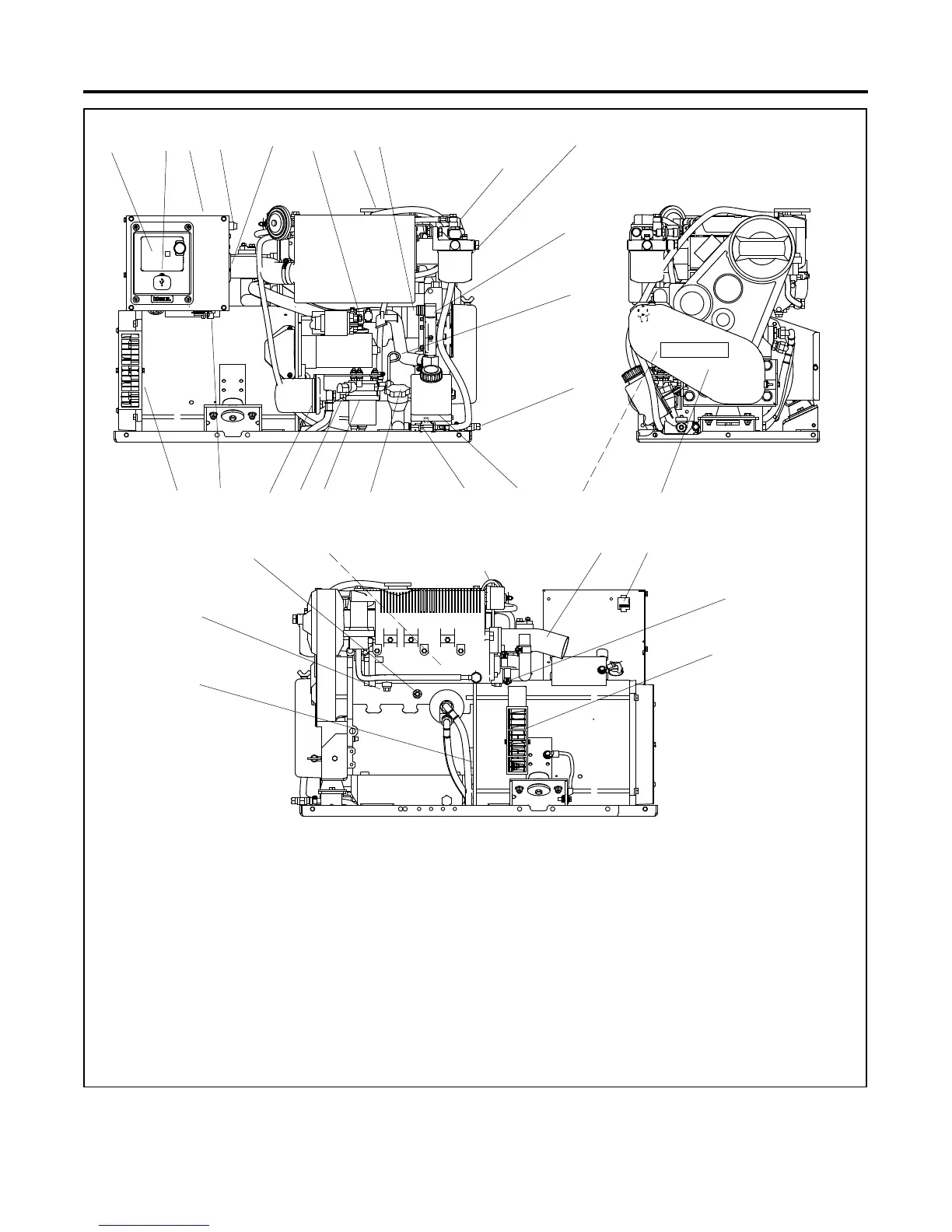
1. ADC-IId controller
2. USB port
3. Nameplate (on top of controller)
4. Fuses (F1, F2, and F3)
5. AC circuit breaker panel
6. Battery positive (+) connection
7. Coolant fill/coolant overflow tube
8. Seawater inlet
9. Fuel solenoid
10. Fuel filter
11. Seawater pump
12. Oil check/dipstick
13. Fuel return
14. Coolant overflow bottle
15. Oil drain valve
16. Oil fill
17. Fuel feed pump
18. Fuel inlet
19. Oil filter
20. Customer load lead connection
21. Alternator cooling air inlet
22. V-belt
23. Belt guard
24. Battery negative (--) connection
25. Seawater drain
26. Engine coolant drain
27. Heat exchanger internal to exhaust manifold
28. Lifting eye
29. Mixing elbow (water outlet/exhaust outlet)
30. Customer interface
31. Anticorrosion zinc anode
32. Air outlet
16
12
14 2315
13
30
2217 16
8
24
7
11
10
5
18
34
29
28
2
20 19
32
Non Service-Side View
ADV7942-A
21
27
25
31
26
9
Figure 1-1 Service Views—Typical
Note:
Consult installation drawings in the spec sheet or installation manual for more details on fuel and battery connection points. Consult an
authorized distributor/dealer or the service manual for items not shown.
 Loading...


