TP-6196 10/09 93Section 6 Component Testing and Adjustment
6.12 Fuel Systems
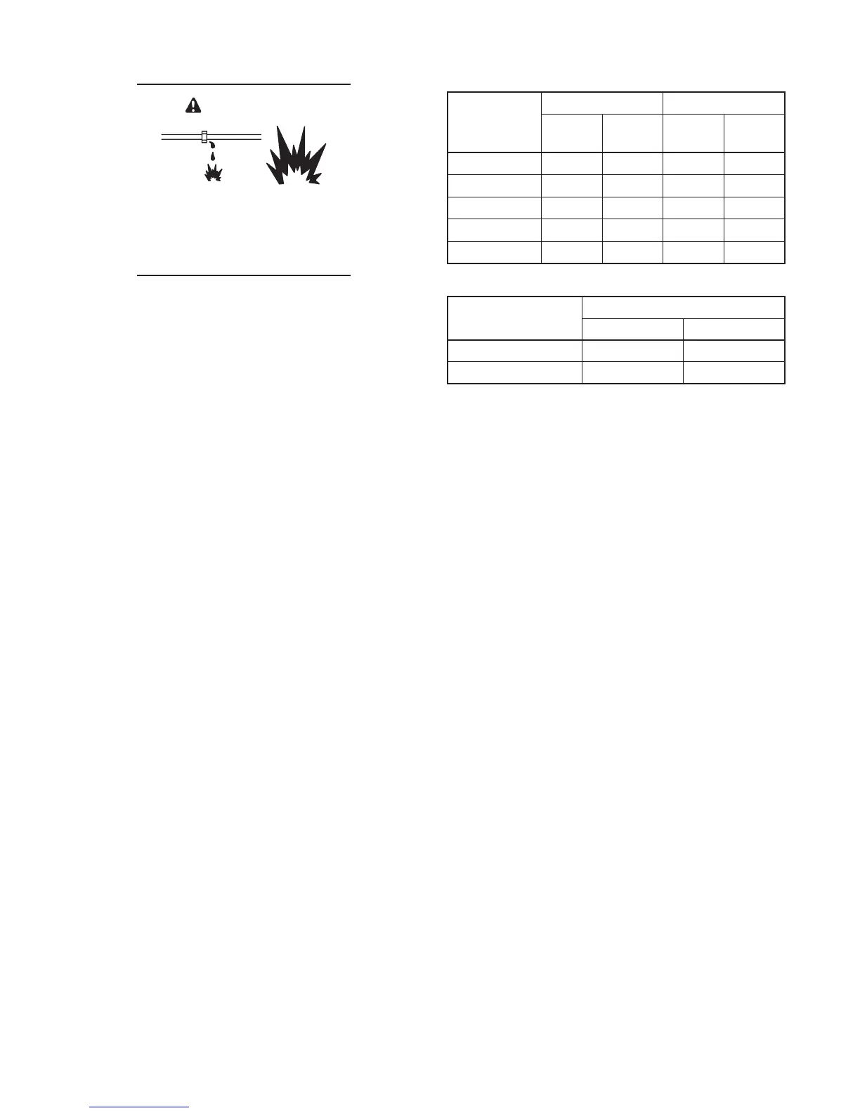
Explosive fuel vapors.
Can cause severe i njury or death.
Use extreme care when handling,
storing, and using fuels.
WARNING
The fuel supplier provides and maintains manual
shut-off valves and the primary regulator. Verify that the
fuel system capacity is adequate to supply the generator
set plus all other gas appliances.
A factory-installed secondary regulator and 12 VDC
solenoid valve are located in the front inlet air
compartment. The controller energizes the fuel
solenoid valve to open at startup and deenergizes the
valve to close at shutdown. The secondary fuel
regulator reduces fuel pressure for delivery to the fuel
metering valve. The fuel flows from the fuel metering
valve to the carburetor in a gaseous state. The
carburetor mixes the fuel with intake air for consumption
by the engine.
Use a universal exhaust gas oxygen (UEGO) sensor to
check the fuel m ixture after replacing the fuel regulator,
fuel mixer, or silencer. The engine should be warm when
the fuel mixture is checked. See Section 6.12.6 for
instructions to check the fuel mixture.
Refer to the troubleshooting instructions in
Section 3,Troubleshooting, to identify generator set
operation problems that may be caused by an
inadequate fuel supply, incorrect adjustments, or
damaged fuel system components. Then use the
instructions in this section to check fuel system
components.
6.12.1 Gas Pipin g
Verify that the gas pipe size meets the size
specifications in Figure 6-32. Measure the pipe length
from the gas utility pressure regulator to the end of the
pipe where it connects to the fuel inlet of the generator
set. Add 2.4 m (8 ft.) for each bend in the pipe.
Compare the total length with the chart in Figure 6-32. If
the piping is longer than the maximum length shown in
the chart, replace it with a larger pipe size. Bleed the air
from the gas lines after installation.
Figure 6-33 lists the maximum gas flow rates for each
model.
Pipe Length,
m (ft.)
8.5RES 12RES
Natural
Gas
LP
Natural
Gas
LP
8 (25) 3/4 1/2 3/4 3/4
15 (50) 3/4 3/4 1 1
30 (100) 1 1 1 1
46 (150) 1 1 1 1/4 1
61 (200) 1 1 1 1/4 1 1/4
Figure 6-32 Maximum Gas Pipe Length
Generator Set Model
Gas Flow Rate, Btu/hr.
Natural Gas LP
8.5kW 132000 180000
12kW 202000 270000
Figure 6-33 Maximum Natural Gas Flow Rate
6.12.2 Fuel Solenoid Valve
A solenoid valve upstream of the regulator and the
flexible fuel connector provides automatic fuel on/off
control. The engine starting battery powers the solenoid
valve and the engine starting controls open the valve
when the engine cranks or runs.
Gas Valve Operation Test Procedure
1. Disconnect the positive (+) battery lead from the
gas valve terminal.
2. Apply 12 VDC to the gas valve terminal and listen
for an audible click, indicating that the valve
actuates.
3. Replace the gas valve if it does not actuate in
step 2.
6.12.3 Fuel Regulators
The typical gaseous fuel system uses two regulators.
The primary regulator reduces the line pressure to an
allowable inlet pressure for the secondary regulator.
The fuel supplier provides and maintains the primary
regulator. The secondary regulator is factory-installed
on the generator set and is designed for a maximum inlet
pressure of 2.7 kPa (6 oz./in.
2
) or 280 mm (11 in.) water
column.
Note: Do not attempt to adjust the fuel mixture or engine
speed by adjusting the regulators.
 Loading...