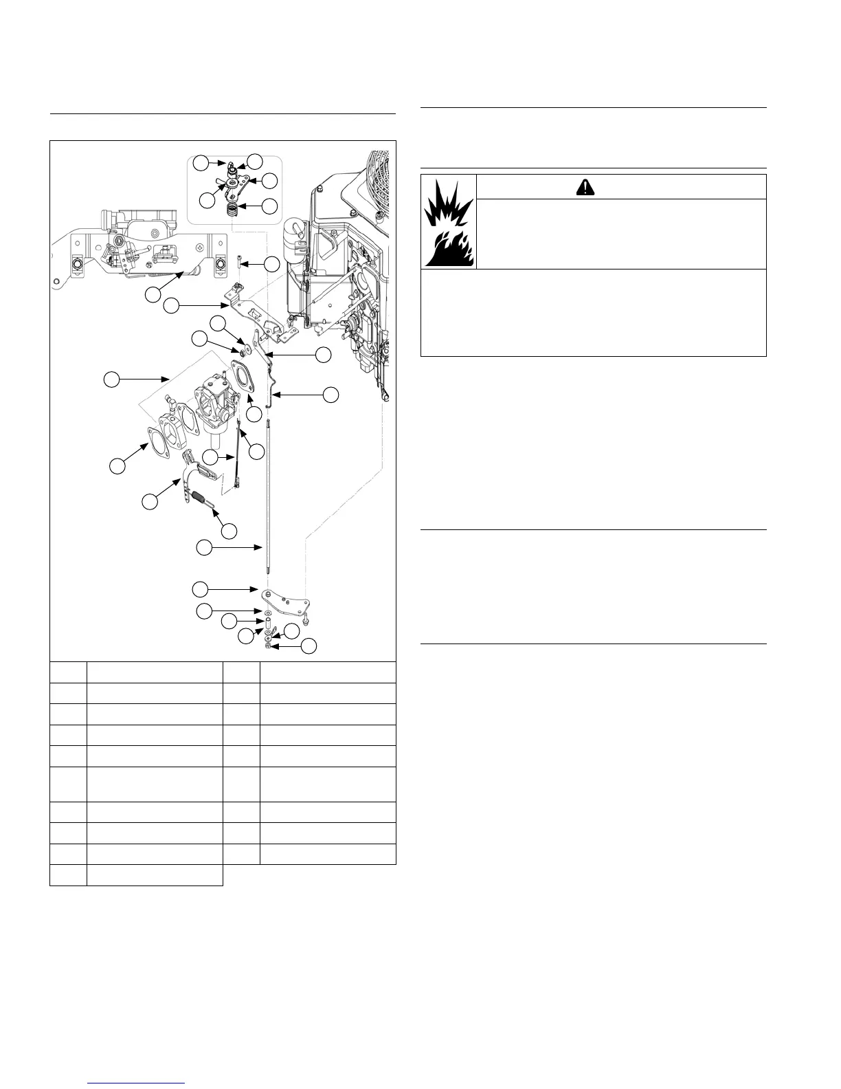
Remove Throttle Controls
Control Panel Components
D
F
D
I
J
P
C
R
N
M
G
H
Q
B
E
S
L
A
B
C
C
K
C
L
B
O
A Nut B Lock Nut
C Flat Washer D Control Bracket
E Carburetor F Air Cleaner Gasket
G Governor Lever H Governor Spring
I Throttle Shaft J Bracket
K Spacer L
Throttle Control
Lever
M Linkage Spring N Throttle Linkage
O Carburetor Gasket P Choke Linkage
Q Choke Lever R Screw
S Throttle Shaft Spring
1. Remove screws securing throttle control bracket and
lower air cleaner bracket (some models), to cylinder
heads.
2. Disconnect spring from governor lever; note hole
locations for reassembly.
3. Remove choke linkage from choke actuator lever
and carburetor.
Remove External Governor Controls
Loosen nut and remove governor lever from cross shaft.
Leave lever attached to throttle linkage.
Remove Carburetor
WARNING
Explosive Fuel can cause res and severe
burns.
Do not ll fuel tank while engine is hot or
running.
Gasoline is extremely ammable and its vapors can
explode if ignited. Store gasoline only in approved
containers, in well ventilated, unoccupied buildings,
away from sparks or ames. Spilled fuel could ignite if it
comes in contact with hot parts or sparks from ignition.
Never use gasoline as a cleaning agent.
1. Disconnect fuel shut-off solenoid lead if equipped.
2. Remove carburetor mounting nuts.
3. Remove carburetor, throttle linkage and governor
lever as an assembly.
4. Remove carburetor gasket.
5. If necessary, carburetor, throttle linkage and
governor lever can be separated. Reattach bushings
to linkage following separation to avoid losing them.
Remove Electric Starter Motor
1. Disconnect leads from starter.
2. Remove screws.
3. Remove starter assembly and lift bracket. Some
inertia drive starters use a separate starter cover
and spacers.
Remove Outer Bafes and Blower Housing
1. Disconnect wire leads from start switch on blower
housing (if equipped). Disconnect plug from rectier-
regulator. Use tip of dipstick or a similar small at
tool to bend locking tang, then remove B+ terminal
from center position in plug. This will allow blower
housing to be removed without disturbing wiring
harness.
2. Rectier-regulator does not have to be detached
from blower housing. If engine is equipped with
SMART-SPARK
™
, remove mounting screws from
spark advance module (SAM). Module will hang
loose as part of wiring harness.
3. Remove screws securing outer bafes. Note location
of any lifting strap and position of short screws (one
each side on bottom) for reassembly.
4. Remove outer bafes.
5. If ywheel screen overlaps blower housing, remove
fasteners and screen. If it was a metal screen with
long bolts, also remove remaining loose hardware
and cooling fan.
6. Remove remaining screws securing blower housing.
Note 1 silver plated screw used for rectier-regulator
ground strap or lead. Remove blower housing.
Disassembly/Inspection and Service
60
24 690 07 Rev. HKohlerEngines.com
 Loading...