5.4
Section 5
EFI Fuel System
Electrical Components
Electronic Control Unit (ECU)
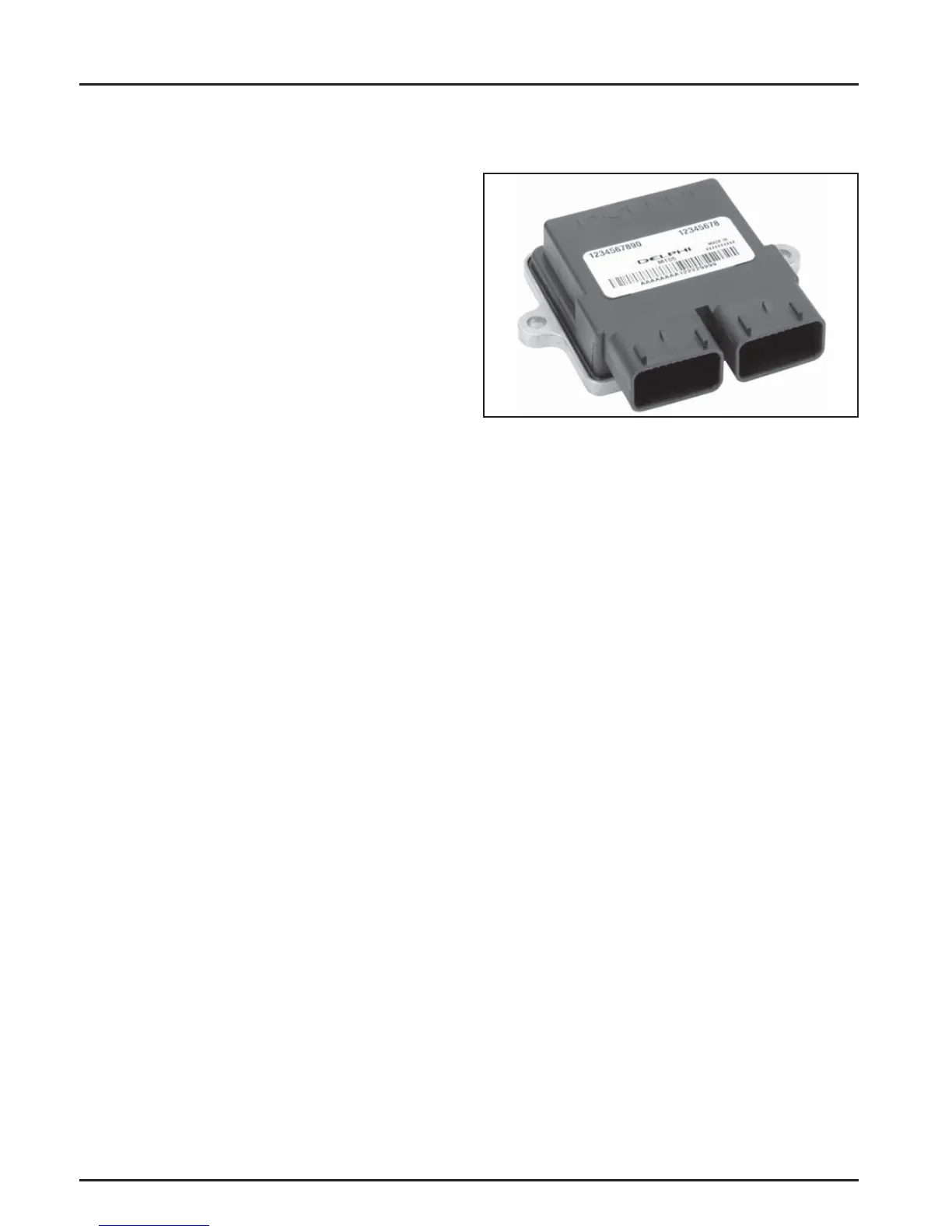
Figure 5-1. Electronic Control Unit (ECU).
General
The ECU is the brain or central processing computer
of the entire EFI system. During operation, sensors
continuously gather data which is relayed through
the wiring harness to input circuits within the
ECU. Signals to the ECU include: ignition (on/
off ), cranksha position and speed (RPM), thro le
position, oil temperature, intake air temperature,
exhaust oxygen levels, manifold absolute pressure,
and ba ery voltage.
The ECU compares the input signals to the
programmed maps in its memory to determine the
appropriate fuel and spark requirements for the
immediate operating conditions. The ECU then sends
output signals to set the injector duration and ignition
timing.
The ECU continually performs a diagnostic check
of itself, each of the sensors, and the system
performance. If a fault is detected, the ECU can turn
on a Malfunction Indicator Light (MIL) (if equipped)
on the equipment control panel, store the fault code
in its fault memory, and go into a default operating
mode. Depending on the signifi cance or severity of the
fault, normal operation may continue. A technician
can access the stored fault code using a blink code
diagnosis fl ashed out through the MIL. An optional
computer so ware diagnostic program is also
available, see Section 2.
The ECU requires a minimum of 6.0 volts to operate.
To prevent engine over-speed and possible failure, a
rev-limiting feature is programmed into the ECU. If
the maximum RPM limit (4500) is exceeded, the ECU
suppresses the injection signals, cu ing off the fuel
fl ow. This process repeats itself in rapid succession,
limiting operation to the preset maximum.
• Always depressurize the fuel system through the
fuel connector on fuel pump module before
disconnecting or servicing any fuel system
components. See fuel warning on page 5.2.
• Never a empt to service any fuel system
component while the engine is running or the
ignition switch is ON.
• Do not use compressed air if the system is open.
Cover any parts removed and wrap any open
joints with plastic if they will remain open for
any length of time. New parts should be removed
from their protective packaging just prior to
installation.
• Avoid direct water or spray contact with system
components.
• Do not disconnect or reconnect the ECU wiring
harness connector or any individual components
with the ignition on. This can send a damaging
voltage spike through the ECU.
• Do not allow the ba ery cables to touch opposing
terminals. When connecting ba ery cables a ach
the positive (+) cable to the positive (+) ba ery
terminal fi rst, followed by the negative (-) cable to
the negative (-) ba ery terminal.
• Never start the engine when the cables are loose
or poorly connected to the ba ery terminals.
• Never disconnect the ba ery while the engine is
running.
• Never use a quick ba ery charger to start the
engine.
• Do not charge the ba ery with the key switch
ON.
• Always disconnect the negative (-) ba ery cable
before charging the ba ery, and also unplug the
harness from the ECU before performing any
welding on the equipment.
 Loading...