5.23
Section 5
EFI Fuel System
5
Throttle Body/Intake Manifold Assembly
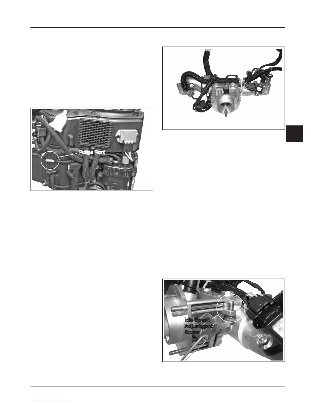
Figure 5-21. Purge Port Location.
General
The vent hose assembly is intended to vent fuel vapor
out of the fuel pump module and direct the fuel vapor
intothethrolebody.AllEFIenginesareequipped
with an engine mounted purge port on the #2 cylinder
barrelbae.Thiscappedpurgeportcanbeusedby
the OEM to vent fuel tanks or used in conjunction
with a carbon canister kit for Tier III evaporative
emissions compliance. The purge port connects to
the vent hose assembly and directs all fuel vapor into
thethrolebody.Ifthepurgeportremainsunused,
the port must remain capped to prevent dirt from
entering the engine. See Figure 5-21.
Service
Nospecicservicingisrequiredfortheventhose
assembly or purge port unless operating conditions
indicate replacement is required. All components
are serviced individually. Abrasion sleeves on hoses
should be reused or replaced when servicing vent
hoses. Please note vent hose routing and replicate
aerserviceorcomponentreplacementtoprevent
pinching or abrasion of the vent hoses.
Service
The high pressure fuel line is mounted to the
intakemanifold.Nospecicservicingisrequired
unless operating conditions indicate that it needs
replacement. It can be detached by removing the two
mounting screws, wire ties, and the injector retaining
clips. Thoroughly clean the area around all joints and
relieve any pressure before starting any disassembly
by following the instruction on page 5.2.
Purge Port and Vent Hose Assembly
Purge Port
Figure 5-22. Throttle Body/Intake Manifold Details.
General
TheEFIengineshavenocarburetor,sothethrole
function(regulateincomingcombustionairow)is
achievedwithathrolevalveinaseparatethrole
bodyaachedtotheintakemanifold.Thethrole
body/intake manifold provides mounting for the
fuelinjectors,throlepositionsensor,intakeair
temperature sensor, high pressure fuel line, idle speed
screw, and air cleaner assembly. See Figure 5-22.
Service
Thethrolebodyisservicedasanassembly,with
thethrolesha,TPS,throleplate,andidlespeed
adjustingscrewinstalled.Thethrolesharotateson
needle bearings (non-serviceable), capped with seals
to prevent air leaks.
NOTE: ECUResetisrequiredifthethrolebodyis
replaced.
Idle Speed Adjustment (RPM)
Idle Speed
Adjustment
Screw
Figure 5-23. Idle Speed Adjustment.
 Loading...