5.18
Section 5
EFI Fuel System
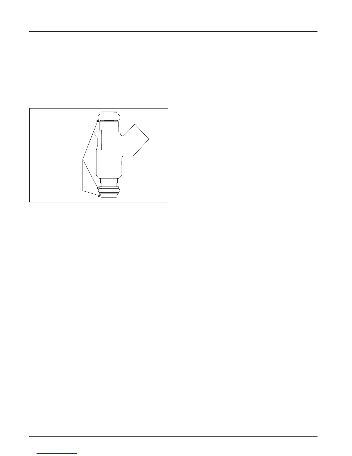
Injector leakage is very unlikely, but in those rare
instances it can be internal (past the tip of the valve
needle), or external (weeping around the injector
O-rings). See Figure 5-15. The loss of system pressure
from the leakage can cause hot restart problems and
longer cranking times. To check for leakage it will be
necessary to loosen or remove the blower housing
which may involve removing the engine from the
unit.
Check for Leaks
11. Disconnect the breather tube on top of the thro le
body.
12. Disconnect the vent hose underneath the thro le
body.
13. Disconnect the rectifi er-regulator connector.
14. Remove the blower housing mounting screws.
Note the location of the plated (silver) screw
a aching the rectifi er-regulator ground bracket.
To gain access to the screw behind the dipstick
tube, remove the dipstick tube screw and pull the
tube out. Remove the blower housing.
15. Thoroughly clean the area around and including
the thro le body/manifold and the injectors.
16. Disconnect the thro le linkage and linkage spring
from the governor lever. Disconnect the TPS lead
from the harness.
17. Remove the manifold mounting bolts and
separate the thro le body/manifold from the
engine leaving the TPS, high pressure fuel line,
injectors and fuel line connections intact. Discard
the old gaskets.
18. Position the manifold assembly over an
appropriate container to capture fuel and turn the
key switch ON to activate the fuel pump and
pressurize the system. Do not turn switch to
START position.
19. If either injector exhibits leakage of more than
two to four drops per minute from the tip, or
shows any sign of leakage around the outer shell,
turn the ignition switch OFF and replace the
injector as follows.
20. Depressurize the fuel system following the
procedure in the fuel warning on page 5.2.
21. Clean any dirt accumulation from the sealing/
mounting area of the faulty injector(s) and
disconnect the electrical connector(s).
22. Pull the retaining clip off the top of the injector(s).
Remove the screw holding the injector(s) from
the manifold.
Figure 5-15. Injector Inspection Points.
1. Engine must be cool. Depressurize fuel system as
stated on page 5.2.
2. Disconnect spark plug leads from spark plugs.
3. Remove the air cleaner by removing the two top
screws and the three nuts securing the air cleaner
base to the thro le body. Service air cleaner
components as required.
4. Remove the fl ywheel grass screen if it overlaps
the blower housing.
5. Remove the two oil cooler mounting screws.
6. Remove the two screws for the pulse pump.
7. Remove the fuse bracket if equipped.
8. Remove one screw securing the ECU bracket into
the blower housing.
9. Remove the top nut, washer and spring for the
thro le control sha and the two screws for the
thro le control bracket.
10. Remove oil separator mounting hardware if
equipped.
 Loading...