5.25
Section 5
EFI Fuel System
5
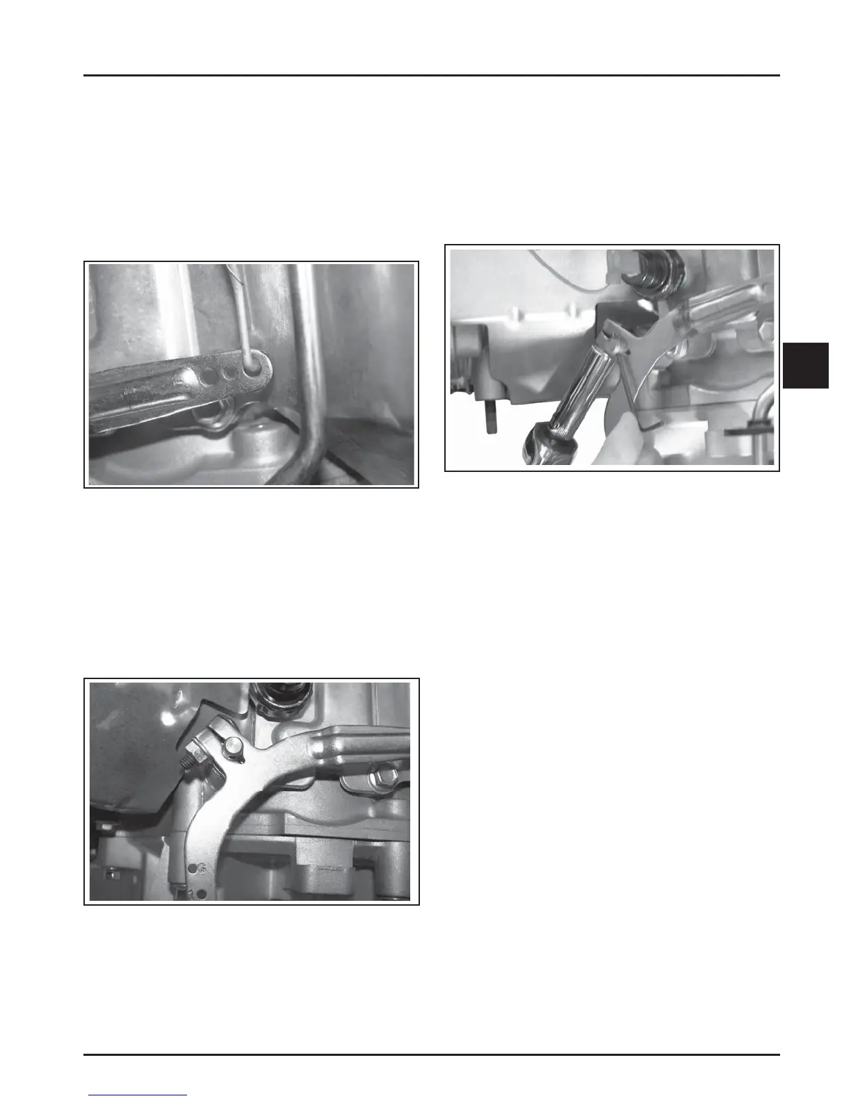
Figure 5-26. Throttle Link in Center of Hole.
B. Setting the Initial Adjustment
1. Check the split where the clamping screw goes
through the governor lever. See Figure 5-27.
There should be a gap of at least 1/32 in. If the
tips are touching and there is no gap present, the
lever should be replaced. If not already installed,
position the governor lever on the cross sha , but
leave the clamping screw loose.
3. Rotate the governor lever and sha
counterclockwise until it stops. Use only enough
pressure to hold it in that position.
4. Check how the end of the thro le linkage aligns
with the bushing hole in the governor lever. See
Figure 5-26. It should fall in the center of the hole.
If it doesn’t, perform the adjustment procedure as
follows.
3. Insert a nail or Allen wrench into the hole in the
top of the cross sha . Using light pressure, rotate
the governor sha counterclockwise as far as it
will turn, then torque the hex nut on the
clamping screw to 6.8 N·m (63 in. lb.). See Figure
5-28. Make sure that the governor arm has not
twisted up or down a er the nut has been
tightened.
Figure 5-27. Checking Split of Clamp.
2. Follow the instructions in Step 2 of Checking the
Initial Adjustment, then rea ach the thro le
linkage to the governor lever with the bushing
clip. It is not necessary to rea ach the damper or
governor springs at this time.
Figure 5-28. Adjusting Governor Shaft.
4. Verify that the governor has been set correctly.
With the linkage still retained in the Full Thro le
position (Step 2), unsnap the bushing clip,
separate the linkage from the bushing, and
remove the bushing from the lever. Follow Steps
3 and 4 in Checking the Initial Adjustment.
5. Reconnect the dampening spring into its
governor lever hole from the bo om. Reinstall
the bushing and rea ach the thro le linkage. See
Figure 5-24. Rea ach the governor spring in the
marked hole.
6. Start the engine and allow it to fully warm up
and establish closed loop operation
(approximately 5-10 min.). Check the speed
se ings and adjust as necessary, fi rst the low idle
speed, and then the high-speed se ing.
NOTE: Thro le body and air cleaner assembly
must be securely fastened with three hex
fl ange nuts to the intake manifold prior to
a empting to set the governor.
 Loading...