7.4
Section 7
Electrical System and Components
Battery Charging System
General
These engines are equipped with a 20 or 25 amp
regulated charging system. See Figure 7-3 for the 20/25
amp charging system diagram.
NOTE: Observe the following guidelines to
avoid damage to the electrical system and
components:
• Make sure the ba ery polarity is correct. A
negative (-) ground system is used.
• Disconnect the rectifi er-regulator plug and/
or the wiring harness plug before doing any
electric welding on the equipment powered by
the engine. Also, disconnect all other electrical
accessories in common ground with the engine.
• Prevent the stator (AC) leads from touching or
shorting while the engine is running. This could
damage the stator.
Stator
The stator is mounted on the crankcase behind
the fl ywheel. Follow the procedures in Section 8 -
Disassembly and Section 10 - Reassembly if stator
replacement is necessary.
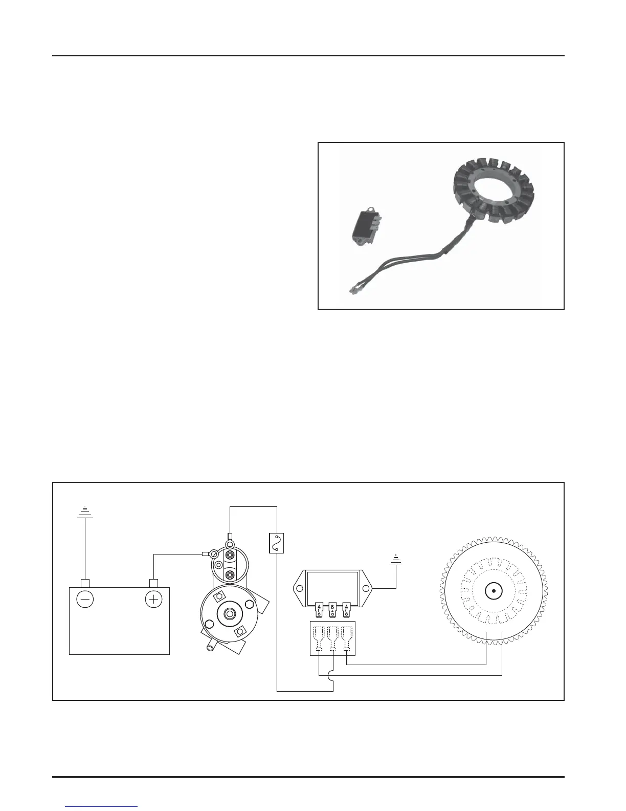
Figure 7-3. Wiring Diagram - 20/25 Amp Regulated Battery Charging System.
20/25 Amp Regulated Charging System
Figure 7-4. 20 Amp Stator and Rectifi er-Regulator.
Flywheel
Stator
Assembly
Connector
Block
Rectifi er-
Regulator
Fuse
Battery
Starter
 Loading...