6 TT-1625 7/17
Common Fault. Red LED flashes slowly when a single
or multiple common fault #1 occurs. Yellow LED
flashes
slowly
when a single or multiple common fault #2
occurs. User Programmed Inputs #1 through #5 can be
assigned to indicate a common fault and are discussed
later in this section. See also Figure 7.
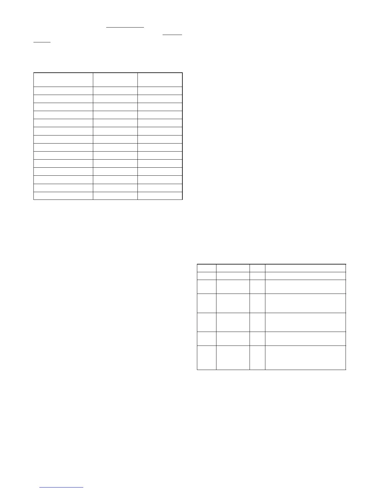
Controller
Assignment
method
Digital input
count
Master RSA III Automatic 5
Slave RSA(s) Not applicable Not accessible
APM802
Via SiteTecht
16
Decision-Makerr 3+ Via SiteTecht
3
Decision-Makerr 550 Via SiteTecht
32
Decision-Makerr 3000 Via SiteTecht
3
Decision-Makerr 3500 Via SiteTecht
6
Decision-Makerr 6000 Via SiteTecht
32
Decision-Makerr 8000 Via SiteTecht
8
KPC 1000 Not applicable 0
MPACr 750 Via SiteTecht
2
MPACr 1000 Via SiteTecht
2
MPACr 1200 Via SiteTecht
2
MPACr 1500 Via SiteTecht
2
Figure 7 RSA III User Defined Inputs and EPS
Supplying Load Defaults
Common faults are s electable on the DEC 550
controller using the respective controller menu choices.
The 550 controller offers two choices for common fault
setup.
D Configure a programmable digital output on the
DEC 550 as a common fault and wire that into one of
the DEC 550’s programmable user inputs 7, 8, or 10.
Use SiteTecht to configure the corresponding RSA
user input source 1, 2, or 3 (P41-2, -4, or -6). This is
the recommended approach s ince another line from
the DEC 550 to the RSA is unnecessary.
D Configure a programmable digital output on the
DEC 550 as a common fault and wire that into the
RSA’s user input source 1, 2, or 3 (P41-2, -4, or -6).
The DEC 3+ controller offers two choices for common
faults using terminal 32 or 32A.
Terminal 32 on the DEC 3+ provides the following ten
common faults:
D Auxiliary Warning
D (Generator Switch) Not-In-Auto
D High Engine Temperature Shutdown
D High Engine Temperature Warning
D Low Water Temperature Warning
D Low Fuel Warning
D Low Oil Pressure Shutdown
D Low Oil Pressure Warning
D Overcrank Shutdown
D Overspeed Shutdown
Terminal 32A on the DEC 3+ provides the following five
common faults:
D Auxiliary Warning
D Emergency Stop
D High Engine Temperature Shutdown
D Low Oil Pressure Shutdown
D Overspeed Shutdown
Communication Status. The RSA III is shipped from
the factory preset as a master device and
communicating with a generator set controller on
Modbusr address #1 and/or ATS controller on Modbusr
address #2 with ATS connected set to False. The
generator set controller is a slave device. Additional
RSA III devices on the same network must be reset in
the field as slave devices. See Figure 6 and Figure 8.
LED LED Status Horn Function
Green Steady on Off Communication is okay
Green Flashes slow Off When communication is being
established
Green Flashes fast Off When the master RSA II
communication configuration does
not match the device
Red Flashes fast On When the master RSA II
encounters a communication
problem with a device
Red Flashes slow On When the slave RSA II does not
detect the master RSA II
Red Steady on On
When the master RSA II is set up
to communicate with the slave
RSA II and the slave RSA II does
not respond to the master RSA II
Figure 8 Communication Status
Note: Should any communication issues occur when
adding RSA III slaves and/or transfer switches to
the system, be sure to power down the RSA III
master and then power up the RSA III master so
that the RSA III master can recognize the
changes.
Modbusr is a registered trademark o
Schneider Electric.
 Loading...


