Roughing-In
Before You Begin
Observe all local plumbing, building, and electrical codes.
Read these instructions and determine all required components along with their installation
locations before beginning this installation.
A licensed electrician should install a 120 V GFCI electrical outlet, within the stud framing, in close
proximity to the electronic valve. The interface(s) is/are powered through the connection(s) with the
valve.
Install the valve prior to installing the interface(s).
Kohler Co. reserves the right to make revisions in the design of faucets without notice, as specified
in the Price Book.
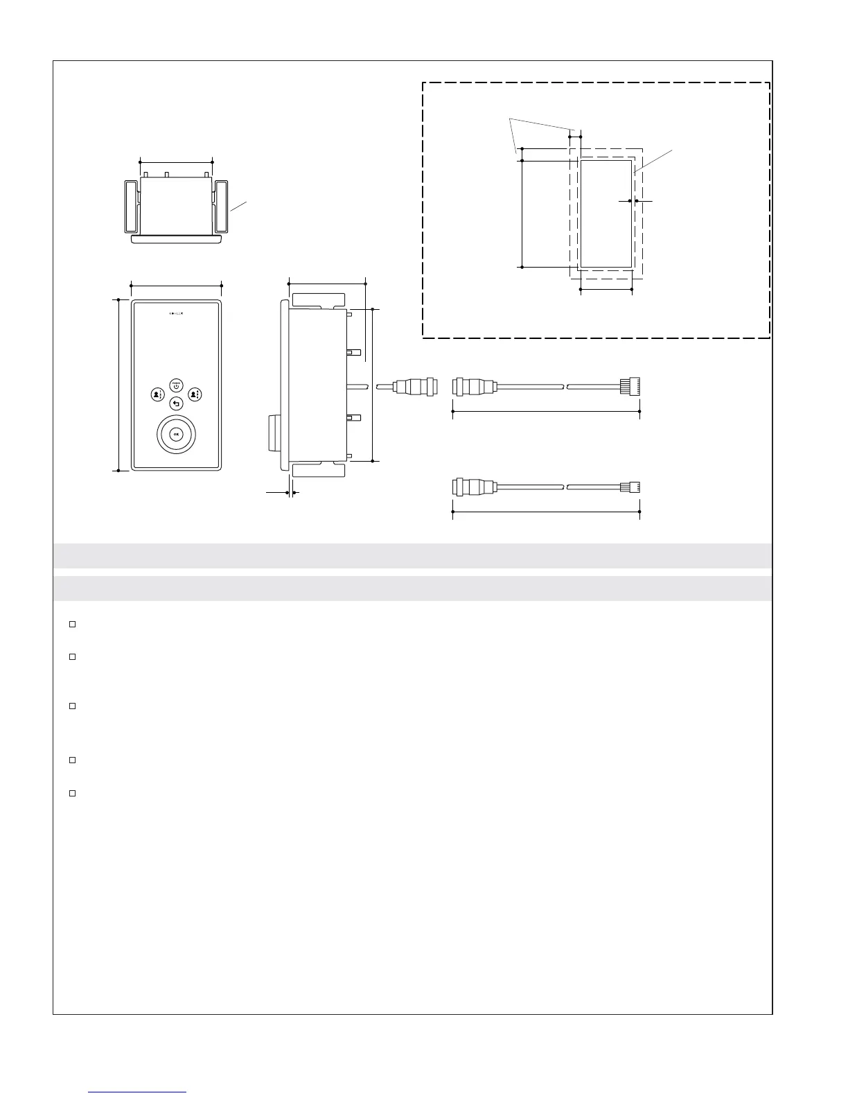
7-5/8"
(19.4 cm)
3-5/8" (9.2 cm)
4-1/2" (11.4 cm)
30' (9.14 m)
30' (9.14 m)
8-Pin Interface Cable
4-Pin Auxiliary Interface Cable
Cutout
7-11/16"
(19.5 cm)
3-11/16" (9.4 cm)
Cutout Detail
1/2" (1.3 cm) Min Clamp
Arm Clearance
1/4" (6 mm) Min
Interface Lip
Clearance
Clamp Arm
8-1/2"
(21.6 cm)
3-5/8" (9.2 cm) –
4-5/8" (11.7 cm)
Wall Cavity
Depth
3/16" (5 mm) Min –
2" (5.1 cm) Max Depth
1043184-2-B 4 Kohler Co.
 Loading...