Scan for full manual
VM-114H2C Quick Start Guide
This guide helps you install and use your VM-114H2C for the first time.
Go to www.kramerav.com/downloads/VM-114H2C
to download the latest user manual and check if firmware
upgrades are available.
Step 1: Check what’s in the box
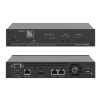
VM-114H2C 2 Input 1:4 HDMI DA/2x CAT5 Outputs
1 Set of rack ears
4 Rubber feet
IR remote control transmitter with batteries
1 Power supply (12V DC)
IMPORTANT NOTICE!
We highly recommend using only
Kramer UNIKAT cables with these products. If using 3
rd
party shielded CAT-6A cables, both ends of the
shield must be soldered to the connectors for the products to function properly. Do not use any jumpers, unshielded wall plat
es or mid-
connections. These extenders are not compatible with HDBaseT technologies. Prior to signal extension, ensure that the
extension line cable is lying straight and not coiled.
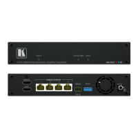
Step 2: Get to know your VM-114H2C
# Feature Function
Sensor for the remote-control IR transmitter
Lights yellow when receiving signals from the IR remote control transmitter
REMOTE IR 3.5mm Mini Jack
Connect to a remote IR sensor
Press (when one of the output LEDs is flashing to indicate a selected output) to read the
selected EDID
Press repeatedly to cycle through the outputs to select from which one to read the EDID.
The relevant LED flashes
The relevant LED lights green when an acceptor is connected to the output
Also lights or flashes during EDID setup (see Section 5.2)
Lights green when the unit receives power
Press to select an input. The relevant IN 1 HDMI/IN 2 CAT5 LED lights
Lights green when HDMI input 1 is selected
Lights green when the TP CAT 5 input 2 is selected
RS-232 9-pin D-sub (F) Connector
Connect to a PC or remote controller
Connect to the +12V DC power adapter, center pin positive
IN1 (HDMI) Input HDMI Connector
Connect to an HDMI source
IN2 (CAT5) Input RJ-45 Connector
OUT 1, OUT 2 HDMI Connector
Connect to the HDMI acceptors
OUT 3, OUT 4 TP RJ-45 Connector
Connect to the TP acceptors
The terms HDMI, HDMI High-Definition Multimedia Interface, and the HDMI Logo are trademarks or registered trademarks of HDMI Licensing Administrator, Inc.