2P7/2R0/3PN
1-5-26
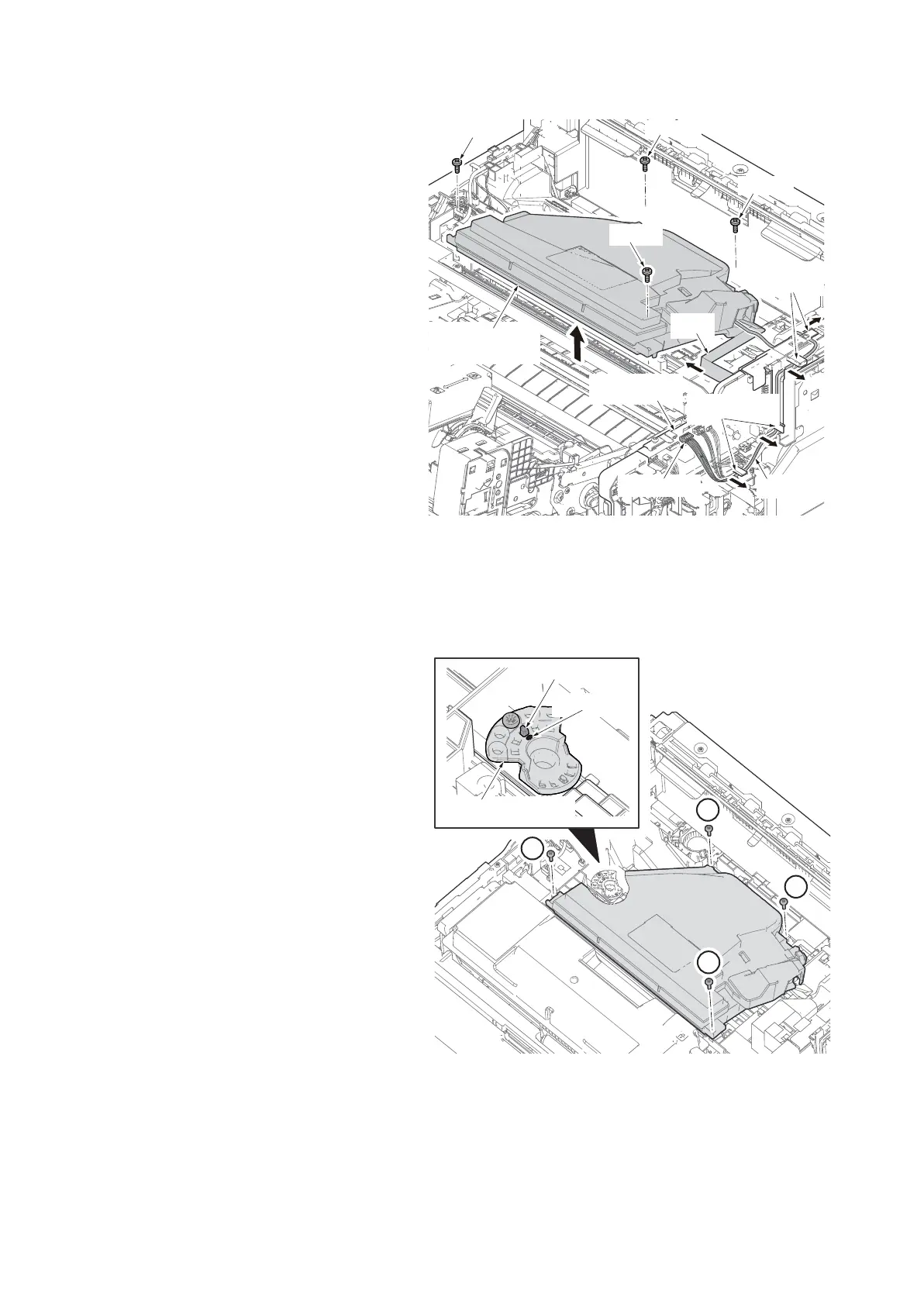
13. Pull the connector and FFC from engine
PWB out.
14. Release the wires from the wire guide.
15. Remove four screws and then remove
the laser scanner unit upward.
16. Check or replace the laser scanner unit
and refit all the removed parts.
Figure 1-5-46
The cautions at the time of refitting the unit
1. Attach the screw in order of 1 to 4.
2. When the positioning holder was removed,
unite the boss part to the marking position
of a positioning holder.
*: Also change a marking position, when a
boss part position is changed at skew
adjustment.
Figure 1-5-47
Screw
Laser scanner
unit
Engin PWB
Wire
FFC
Connector
Screw
Screw
Wire guides
Screw
Wire guides
1
2
3
4
Boss part
Positioning holder
Marking
 Loading...